10
ENGLISH
DO NOT let children come into contact with the tool.
Supervision is required when inexperienced operators use
thistool.
• Young children and the infirm. This appliance is not
intended for use by young children or infirm persons
withoutsupervision.
• This product is not intended for use by persons (including
children) suffering from diminished physical, sensory or
mental abilities; lack of experience, knowledge or skills
unless they are supervised by a person responsible for their
safety. Children should never be left alone with thisproduct.
ASSEMBLY AND ADJUSTMENTS
WARNING: To reduce the risk of serious personal
injury, turn tool off and disconnect battery pack
before making any adjustments or removing/
installing attachments or accessories. An accidental
start-up can causeinjury.
WARNING: Use only DeWALT battery packs andchargers.
Inserting and Removing the Battery Pack
from the Tool (Fig. B)
NOTE: Make sure your battery pack
6
is fullycharged.
To Install the Battery Pack into the Tool Handle
1. Align the battery pack
6
with the rails inside the tool’s
handle (Fig.B).
2. Slide it into the handle until the battery pack is firmly seated
in the tool and ensure that you hear the lock snap intoplace.
To Remove the Battery Pack from the Tool
1. Press the release button
5
and firmly pull the battery pack
out of the toolhandle.
2. Insert battery pack into the charger as described in the
charger section of thismanual.
Fuel Gauge Battery Packs (Fig. B)
Some DeWALT battery packs include a fuel gauge which
consists of three green LED lights that indicate the level of
charge remaining in the batterypack.
To actuate the fuel gauge, press and hold the fuel gauge
button
13
. A combination of the three green LED lights will
illuminatedesignating the level of charge left. When the level
of charge in the battery is below the usable limit, the fuel gauge
will not illuminate and the battery will need to berecharged.
NOTE: The fuel gauge is only an indication of the charge left on
the battery pack. It does not indicate tool functionality and is
subject to variation based on product components, temperature
and end-userapplication.
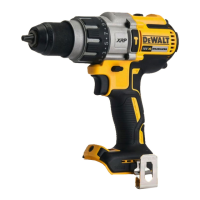
Belt Hook and Magnetic Bit Holder (Fig. A)
WARNING: To reduce the risk of serious personal
injury, turn tool off and disconnect battery pack
before making any adjustments or removing/
installing attachments oraccessories.
WARNING: To reduce the risk of serious personal
injury, DO NOT suspend tool overhead or suspend
objects from the belt hook. ONLY hang tool’s belt hook
from a workbelt.
WARNING: To reduce the risk of serious personal
injury, ensure the screw holding the belt hook issecure.
IMPORTANT: When attaching or replacing the belt hook or
magnetic bit holder, use only the screw
9
that is provided. Be
sure to securely tighten thescrew.
The belt hook
8
and magnetic bit holder
12
can be attached
to either side of the tool using only the screw
9
provided,
to accommodate left- or right- handed users. If the hook or
magnetic bit holder is not desired at all, it can be removed from
thetool.
To move belt hook or magnetic bit holder, remove the screw
9
that holds it in place then reassemble on the opposite side. Be
sure to securely tighten thescrew.
OPERATION
Instructions for Use
WARNING: Always observe the safety instructions and
applicableregulations.
WARNING: To reduce the risk of serious personal
injury, turn tool off and disconnect battery pack
before making any adjustments or removing/
installing attachments or accessories. An accidental
start-up can causeinjury.
Proper Hand Position (Fig. A, C)
WARNING: To reduce the risk of serious personal injury,
ALWAYS use proper hand position asshown.
WARNING: To reduce the risk of serious personal
injury, ALWAYS hold securely in anticipation of a
suddenreaction.
Proper hand position requires one hand on the main
handle
10
.
Variable Speed Trigger Switch (Fig. A)
To turn the tool on, squeeze the trigger switch
1
. To turn the
tool off, release the trigger switch. Your tool is equipped with a
brake. The tool will stop when the trigger switch is fullyreleased.
The variable speed switch enables you to start the application at
a slow speed. The further you squeeze the trigger, the faster the
tool will operate. For maximum tool life, use variable speed only
for starting holes orfasteners.
NOTE: Continuous use in variable speed range is not
recommended. It may damage the switch and should
beavoided.
Forward/Reverse Control Button (Fig. A)
A forward/reverse control button
2
determines the direction of
the tool and also serves as a lock-offbutton.
To select forward rotation, release the trigger switch
1
and
depress the forward/reverse control button
2
on the right side
of thetool.
To select reverse, release the trigger switch
1
and depress
the forward/reverse control button
2
on the left side of the
 Loading...