57
ENGLISH
57
and is subject to variation based on product components,
temperature and end-userapplication.
• The state of charge indicator LEDs
18
will illuminate,
indicating the percent of charge in the batteries.
• When all 5 state of charge indicator LEDs
18
illuminate, the
batteries are fully charged.
• When one state of charge indicator LED
18
illuminates,
charge is low and then it will flash when the batteries
aredischarged. Remove thebatteries and charge them.
State of Charge Indicator LED Status
LEVEL OF CHARGE
CHARGE INDICATOR
LED COLOR
100% ‑ 85% White
70% ‑ 85% White
50% ‑ 70% White
25% ‑ 50% White
≤25% White
Low battery shutdown White and blinking
Handle Folding Indicator (Fig. U)
The handle folding indicator
15
will illuminate when the
single touch handle
1
is not engaged in the operating
position. To clear the handle folding indicator
15
, refer to the
Raise the Single Touch Handle section inthismanual.
Cutting Load Meter Indicator (Fig. U)
The cutting load meter indicator
14
will illuminate white,
yellow or red when mowing.
• White indicates a low cutting load.
• Yellow indicates a medium cutting load.
• Red indicates a high cutting load. Runtime will be reduced if
there is a prolonged high load while mowing.
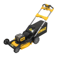
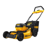
Control Panel Indicators (Fig. A, U)
The control panel
12
contains the state of chargeindicator,
load meter indicator, temperature indicator, handle folding
indicator, blade sharpening indicator and reset button.
State of Charge Indicator (Fig. U)
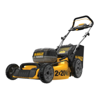
The DCMWP134 and DCMWSP156 are equipped with a state of
charge indicator. This will display the current level of charge in
the batteries during use. It does not indicate tool functionality
Safety Key (Fig. T)
DANGER: Sharp moving blade. In order to prevent
accidental start-up or unauthorized use of your cordless
mower, a removable safety key has been incorporated into
the design of your mower. The mower will be completely
disabled when the safety key has been removed from
themower.
DANGER: Rotating blades can cause serious injury.
To prevent serious injury, turn unit off and remove
safety key and battery packs when unattended, or when
charging, cleaning, servicing, transporting, lifting, or
storingmower.
1. Insert safety key
6
into the key slot
50
, located on the main
handle
4
, until it is fully seated inside of the keyslot
50
as
shown in Fig. T.
2. The mower is now operational.
NOTE: Ensure both battery packs are fully seated and fully
latched intoposition before startingmower.
3. Close the battery port cover
19
. Ensure the cover is fully
closed before startingmower.
To Remove the Battery Packs
1. Lift and hold the battery port cover
19
up to expose the
battery port
38
.
2. Depress the battery release button
27
on the
batterypacks
26
and pull the battery packs out ofthe
batteryport
38
.
Fuel Gauge Battery Packs (Fig. C)
Some DeWALT battery packs include a fuel gauge, which
consists of three green LED lights that indicate the level of
charge remaining in the batterypack.
To actuate the fuel gauge, press and hold the fuel gauge
button
62
. A combination of the three green LED lights will
illuminate, designating the level of charge left. When the level
of charge in the battery is below the usable limit, the fuel gauge
will not illuminate and the battery will need to berecharged.
NOTE: The fuel gauge is only an indication of the charge left on
the battery pack. It does not indicate tool functionality and is
subject to variation based on product components, temperature
and end-userapplication.
 Loading...