GDCA
Ant. L t.
HEB
G nd.
Pwr.
F
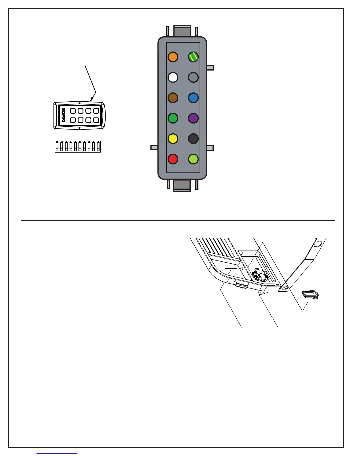
1. GN/YLW Connect to LT GREEN/YELLOW WIRE from LIGHT RELAY
2. GRAY Connect to VALVE H (3rd bank option only)
3. BLUE Connect to VALVE E
4. PURPLE Hook to PURPLE SWITCH WIRE and Connect to VALVE B
5. BLACK Connect to GROUND
6. LT. GREEN Connect to ANTENNA**
7. RED Connect to POWER
8. YELLOW Connect to VALVE A
9. GREEN Connect to VALVE C
10. BROWN Hook to BROWN SWITCH WIRE and Connect to VALVE D
11. WHITE Connect to VALVE G (3rd bank option only)
12. ORANGE Connect to VALVE F
(Rear Side of Male Plug - Deutsch Connector)
1 2 3 4 5 6
7 8 9 10 11 12
RF Receiver
Antenna
DIP S WIT C HE S
UNDE R B AC K C OVE R
FCC
FCC
DewEze
Manual
Switches
Installation Instructions:
1. Bolt left side of RF Receiver through existing hole in headache rack .
Drill hole for right side, if necessary, and attach with bolt.
2. Mount triangular bracket with self-tapping screws (if welded bracket
is not present). Use rubber grommets and 1/2" screw to attach antenna.
3. Run light green wire from receiver through hole in headache rack
and attach to antenna. Drill hole, if necessary.
NOTE: Metal objects such as cake feeders or fuel tanks may interfere
with radio waves from transmitter. The antenna may be moved to the
top of the headache rack, or a second antenna may be installed in a
different location to increase reception.
VERSION II RF RECEIVER
4. Mount manual switches through
holes in headache rack. Attach decal.
Cover all switches and relays with
plasticized undercoating.
5. Set dip switches in transmitter to match dip switches in receiver.
Use serial no. stickers to record ON/OFF positions and attach to
both receiver and transmitter for future reference.
6. If the Deutsch Connector needs to be assembled, insert colored
wires into the numbered positions as described below.
7. Connect the colored wires to the valve as indicated below.
See the following wiring diagrams for 2 and 3 bank wiring.
NOTE: The manual switches
must be protected with
rubber boots. The boots
must be installed with the
correct stem length on the
lever so the they are not
stretched when the switch
is used. This is done by
adjusting the jam nut on
the lever stem.
ON OFF
 Loading...