Do you have a question about the Deye BOS-G Series and is the answer not in the manual?
Manual applies to modular battery energy storage system and its installation.
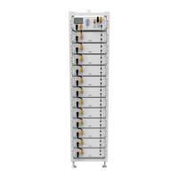
Details BOS-G models, system energy, rated power, and composition.
Explains danger, warning, and attention symbols used in the manual.
Details symbols on equipment for chemical burns and explosion risks.
Covers hot surface, no fire, no object insertion, and safety goggles warnings.
Provides essential safety guidelines for operating the BOS-G system.
States liability limitations for personal injury, property loss, or product damage.
Specifies temperature, humidity, altitude, and fireproof room requirements.
Information on where to download the quality certificate.
Defines required training and knowledge for installation technicians.
Lists critical rules to follow when working with live parts of the system.
Provides safety precautions against electric shock and short circuits.
Prohibits installation in explosive or high-humidity areas and outlines startup/shutdown safety.
Warns about dangers of death or injury from improper use or handling.
Covers regulations and provisions for shipping lithium-ion products.
Details warnings for vehicle transport, tilting, and handling of battery racks.
Emphasizes careful handling, packaging checks, and PPE for safe transport.
Specifies permissible and impermissible positions for storing packaged battery modules.
Battery modules must be transported in an upright position due to top-heavy design.
General precautions before starting the installation process for the system.
Overview of the BOS-G system's features, capabilities, and modular design.
Lists key technical specifications including energy, power, chemistry, and operating parameters.
Lists all necessary tools required to perform the installation of the system.
Lists auxiliary tools and materials needed for assembly and installation.
Identifies and describes the individual parts of the 3U-HRack system.
Step-by-step instructions for assembling the rack frame using provided components.
Identifies the ports and connections on the BOS-G battery module.
Identifies the ports, switches, and indicators on the control box.
Details the function of each port and indicator on the high-voltage control box.
Illustrates the placement of battery modules and the high-voltage control box within the rack.
Illustrates the placement of battery modules and the high-voltage control box within the rack.
Defines the communication interfaces between the PCS and the battery system.
Provides instructions for installing the battery modules into the rack.
Provides instructions for installing the battery modules into the rack.
Defines the communication interfaces between the PCS and the battery system.
Emphasizes grounding importance and safety steps before battery installation.
Warns about battery weight and provides installation cautions.
Visual guide showing the correct sequence for inserting battery modules into the rack.
Details the procedure for connecting the grounding harness and cables.
Describes power and communication cables connecting battery modules and control box.
Specific overcurrent protection requirement for the Australian market.
Diagram illustrating the wiring of a single battery cluster to the inverter.
Diagram illustrating the wiring of two battery clusters to the inverter.
Diagram illustrating the wiring of three battery clusters to the inverter.
Step-by-step instructions for safely starting the BOS-G system.
Step-by-step instructions for safely shutting down the BOS-G system.
Procedure for initial system configuration after installation.
Steps to access the system maintenance interface via password entry.
Procedure to set the number of battery management units (BMUs) in the system.
Information regarding the use of an external 12V power supply for the control box.
Description of the default interface displayed upon system power-on.
Explains icons for Wi-Fi, system maintenance, voltage, current, SOC, and total energy.
Details how faults like overvoltage, undervoltage, and overtemperature are displayed.
Guides on how to view specific fault details after initial indication.
Safety steps required before accessing the maintenance interface.
Lists faults related to overcurrent, overtemperature, and undervoltage during charge/discharge.
Lists faults related to temperature limits, voltage anomalies, and insulation.
Lists faults concerning communication failures, BMU issues, and other system errors.
Summarizes fault types as they appear on the screen and HVESS-Monitor.
Summarizes fault types as they appear on the screen and HVESS-Monitor.
Summarizes fault types as they appear on the screen and HVESS-Monitor.
Warns about potential damage from improper decommissioning before maintenance.
Details annual inspection and maintenance tasks for the BOS-G system.
Specifies tightening torques for electrical connections during maintenance.
Step-by-step guide for upgrading system firmware using a USB drive.
Specifies conditions for storing battery modules to ensure service life.
Instructions to minimize self-discharge and protect batteries during long storage.
Provides information and regulations for the proper disposal of battery modules.
Electrical diagram for an on-grid system incorporating a 12V supply.
Illustrates the complete system wiring, showing connections between modules and inverter.
Contains legal statements, revision history, and manufacturer details for the manual.
| Series | BOS-G Series |
|---|---|
| Category | Storage |
| Nominal Voltage | 51.2V |
| Operating Voltage Range | 44.8V - 57.6V |
| Capacity | 100Ah |
| Nominal Energy | 5.12kWh |
| Usable Capacity | 100Ah |
| Usable Energy | 5.12kWh |
| Operating Temperature | -10°C to 50°C |
| IP Rating | IP20 |
| Warranty | 10 years |
| Battery Type | LFP (Lithium Iron Phosphate) |
| Cycle Life | 6000 cycles at 80% DOD |
| Communication | RS485, CAN |
| Certification | CE, UN38.3 |