11
Quick Setup Guide
Quick Setup
Guide
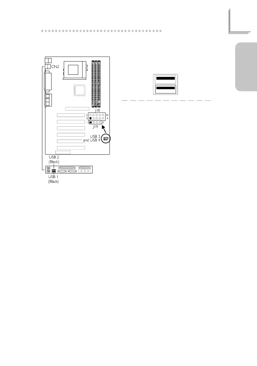
1.3.3 Universal Serial Bus Ports
1 VCC
3D3-
5 D3+
7 GND
9 GND
2 GND
4 GND
6D2+
8D2-
10 VCC
J19
1 VCC
2 D2-
3D2+
4 GND
J18
Depending on the type of USB port cable that you are using, the J18/J19
connector on the system board allows you to connect the optional 3rd
and 4th USB ports.
Insert the USB port cable connector only to J18 if:
Pins 1 and 10 of the cable connector is VCC (red colored edge of the
cable); or
None of the holes on the cable connector is plugged, meaning the
cable connector has no keying mechanism.
Insert the USB port cable connector to pins 1-3-5-7-9 of J18 and pins
1-2-3-4 of J19 if:
One of the holes on the cable connector is plugged, meaning the cable
connector has a keying mechanism; or
Pin 1 of J18 and pin 1 of J19 is VCC (red colored edge of the cable).
Onboard USB Ports (CN2)
Additional USB Ports (J18 and J19)
 Loading...