18
Quick Setup Guide
Quick Setup
Guide
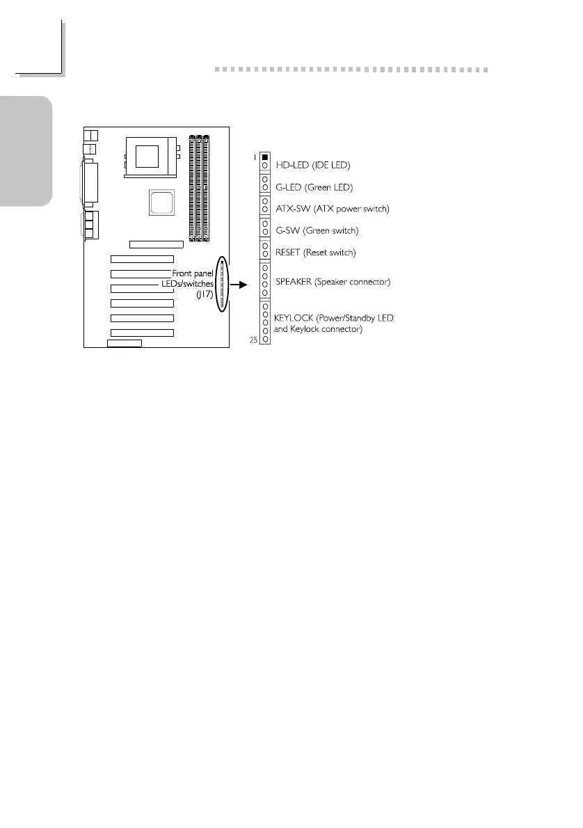
1.3.14 Front Panel Connectors
1 HDD LED Power
2 HDD
3 N. C.
4 Green LED Power
5 Green
6 N. C.
7 PWRBT+
8 PWRBT-
9 N. C.
10 SMI
11 Ground
12 N. C.
13 H/W Reset
Use pins 21-23 for the Power/Standby LED.
14 Ground
15 N. C.
16 Speaker Data
17 N. C.
18 Ground
19 Speaker Power
20 N. C.
21 LED Power (+)
22 N.C.
23 LED Power (-) or
Standby Signal
24 Keylock
25 Ground
If a system did not boot-up and the Power/Standby LED did not light
after it was powered-on, it may indicate that the CPU or memory module
was not installed properly. Please make sure they are properly inserted
into their corresponding socket.