Do you have a question about the DFI lanparty dk P45 series and is the answer not in the manual?
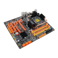
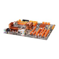
Detailed technical specifications of the motherboard and its features.
Configuration of jumpers on the motherboard for various system settings.
Procedure to reset BIOS settings to default values by clearing CMOS data.
Configuring power options for PS/2 keyboard and mouse for system wake-up.
Configuring power options for USB devices to enable system wake-up functionality.
Setting the Front Side Bus (FSB) speed for the CPU via jumpers.
Resets manageability register bits in the RTC by using a specific jumper.
Description and usage of PS/2 keyboard/mouse and S/PDIF audio ports.
Details on USB connectivity options and the onboard LAN port.
Details on audio connectors and CD-in functionality.
Connectors for center/subwoofer, rear, side speakers, and line-in/out.
Overview of internal input/output connectors on the motherboard.
Connectors for Serial ATA drives and information on RAID configuration.
Details on connecting floppy disk drives and IDE hard drives.
Information on IrDA and Serial (COM) port connectors.
Connector for attaching an IrDA module for infrared communication.
Connector for connecting serial devices like modems and printers.
Connectors for system and CPU fans to ensure proper cooling.
Onboard power and reset switches for user convenience during system setup.
Explanation of system status indicators: DRAM Power LED, Standby Power LED, Diagnostic LED.
Guide to connecting the ATX12V power supply unit to the motherboard.
Procedure for safely powering off and restarting the system to prevent damage.
Details on front panel connectors including LEDs, switches, and speaker.
Information on the location and types of PCI Express expansion slots.
Connector for downloading and flashing the system BIOS.
Description of different RAID configurations: RAID 0, RAID 1, RAID 0+1, and RAID 5.
Required settings in BIOS and OS to enable RAID functionality.
Instructions for physically connecting Serial ATA drives to the motherboard.
Steps to configure Serial ATA settings within the Award BIOS utility.
Procedure for installing RAID drivers during Windows OS installation.
Instructions for installing the Intel Matrix Storage Manager software in Windows.
Troubleshooting abnormal POST codes and system boot failures.
Detailed steps to clear CMOS data using jumpers or by discharging the motherboard.
Procedure to fully discharge the motherboard by removing AC power and the battery.
| Chipset | Intel P45 |
|---|---|
| CPU Socket | LGA 775 |
| Supported CPUs | Intel Core 2 Quad, Core 2 Duo, Pentium, Celeron |
| FSB | 1600/1333/1066/800 MHz |
| Memory Type | DDR2 |
| Memory Slots | 4 |
| Max Memory | 16 GB |
| PCIe 2.0 x16 Slots | 2 |
| PCI Slots | 2 |
| PCIe x1 Slots | 2 |
| SATA Ports | 6 |
| IDE Ports | 1 |
| Dual LAN | No |
| Form Factor | ATX |
| Memory Speed | 1200/1066/800/667 MHz |
| LAN | Realtek RTL8111C |
| USB Ports | 12 |