Do you have a question about the Dhollandia DH-RP.06 and is the answer not in the manual?
| Brand | Dhollandia |
|---|---|
| Model | DH-RP.06 |
| Category | Automobile Accessories |
| Language | English |
Indicates an imminently hazardous situation.
Indicates a potentially hazardous situation.
Indicates a potentially hazardous situation.
Addresses practices not related to physical injury.
General instructions relative to safe work practices.
Alerts user to potential hazards.
Failure to follow instructions risks injury or death.
Confirm the most up-to-date manual version.
DHOLLANDIA disclaims liability for various issues.
Improper use risks serious injury or death.
Improper use risks serious injury or death.
Shows label example with serial number.
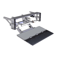
Tail lifts are state-of-the-art, comply with CE regulations.
Mounted in fixed position under vehicle chassis.
Used to mount the lift frame to the vehicle chassis.
Carries load during loading/unloading.
Inboard section of foldable platform.
Foldable, outboard section of platform.
Actuated by hydraulic cylinders to lift/lower platform.
Hydraulic cylinders used to lift/lower platform.
Parallel arms supporting the platform.
Contains motor, oil tank, and control valves.
Controls to lift/lower platform.
Under run protection device.
Point up to which capacity is valid.
Arm assisting platform deployment.
Heavy duty steel extension mounted to vehicle floor.
Steps to help driver climb into vehicle.
Rubber buffers to reduce impact damage.
Steel channels welded to vehicle body.
Steel profiles linking side steps and dock bumpers.
Lock oil inside cylinders to secure platform.
Optional locks to secure platform in travel position.
Limits lift capacity and protects against overload.
Ensure platform lowers at safe speed.
Indicates point for maximum rated capacity.
Compulsory 2-hand operation for safety.
Switches electrical power to tail lift on/off.
Protect electrical circuits against short-circuits.
Prevents crushing of toes/feet.
Optional controls to immobilize feet safely.
Prevents loads from rolling off the platform.
Ensures platform is visible from all sides.
For applications with risk of falling off platform.
Operation, load, and safety decals.
Use restricted to skilled, trained operators.
Use appropriate work clothes, avoid loose clothing.
Park vehicle safely, apply parking brake, deploy stabilizers.
Optional platform lights/flags for visibility.
Check tail lift safety, inspect prior to use.
Keep visual control of working area, avoid pinch points.
Secure loads, use cart-stops.
Do not move vehicle with tail lift open.
Be aware of vehicular traffic.
Use common sense, understand manual.
Impact by platform/moving parts causes injury/death.
Beware of crushing zones.
Risk of pinching, crushing, shearing.
Zone for safe operation of platform.
Use with caution to avoid crushing/shearing.
Fix feet to platform, use with caution.
Conditions for use with spiral cable.
Used inside vehicle body, not on platform.
Do not stand in front/behind load.
Maintain 3 points of contact when riding.
Recommends safety rails for falling prevention.
Improper use may cause damage or injury.
Comply with loading instructions for durability.
Damaged/improperly serviced lifts pose risk.
Information on authorized service agents.
Items to check before operation.
Regular maintenance is essential.
Falling platform causes serious injury or death.
Max capacity valid at center point, not entire surface.
Overloading causes risk of injury/death.
Weight limit at center of gravity.
Avoid concealed overload situations.
Lower load to prevent shifting.
Do not drop loads or drive forklifts onto platform.
Describes platform movement during lifting/lowering.
Platform tilts down/up progressively.
Level ride with automatic tilt at ground level.
Secure loads, especially on half-dip ride.
Platform tilts automatically at ground level.
Platform tilts down/up progressively.
Platform tilts automatically at ground level.
Use auxiliary controls for LIFT/LOWER only.
Misuse of 3/4 button controls causes errors/injury.
Compensate for platform deflection.
Platform deflection causes instability.
Describes different control box models.
Describes different control box models.
Operation of joystick and rotary switches.
Operation of push buttons and safety switch.
Switches main power on/off.
Shows function operation for controls.
Operation of stabilizing legs.
Controls with 2-hand features.
Details popular auxiliary control options.
Use auxiliary controls from safe position.
Handheld controls with spiral cable.
Foot controls on platform.
Controls with toggle switches.
Foot controls on platform.
Switching the tail lift's main power on or off.
Switches power via cabin.
Switches power via external control box.
Combined system requires both switches ON.
Sequence of operations for the tail lift.
Steps to deploy the platform.
Steps for loading and unloading.
Steps to fold and stow platform.
Guidance on using stabilizing legs.
Manually deployed/stowed legs.
Operated via external control box.
Use of stabilizing legs is mandatory on certain vehicles.
Operation of mechanical/hydraulic legs.
Ensuring loads are secured with cart stops.
Secure loads to prevent shifting or falling.
Discussion of popular cart stop models.
Manual cart stops operated by springs.
Automatic cart stops operated by springs.
Vertical cart stops operated by springs.
Affixing and replacing decals.
Overview of warning symbols and their meaning.
Required actions to ensure safety.
Signs indicating prohibited actions.
Common symbols for operations and states.
Summary video and instructions.
Importance of regular preventative maintenance.
 Loading...