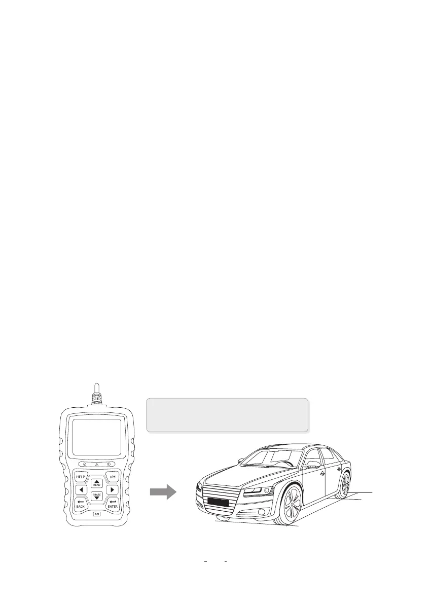
3.1 Connecting to Vehicle
3 Getting Staed
2.2 Accesso Descriptions
This section lists the accessories that go with the code reader. If you nd any of the following items
missing from your package, contact your local dealer fo assistance.
1 User’s Guide- Provides operation instructions for the usage of the code reader.
2 USB Cable- Provides connection between the code reader and a computer to upgrade the tool.
2.3 Technical Specications
Display: 2.8” TFT color display
Working Temperature: 0 to 60°C (32 to 140°F)
Storage Temperature: -20 to 70°C (-4 to 158°F)
Powerr Supply: 8-18V vehicle power
Suppoed Protocols: J1850-PWM / J1850-VPW / ISO9141 / KWP2000 (ISO 14230), and CAN
(Control Area Network ISO 11898)
Dimesions(L×W×H): 147 × 90 × 30mm
Weight: 0.35kg
K BACK Key- Cancels an action and returns to previous screen or level.
L ENTER Key- Conrms an action or movement and moves to next level.
H HELP Key - Accesses to the Help function and it is also used to update the code reader when long
pressed.
N Resta- Resta the code reader.
P USB Po- Provides a USB connection between the code reader and PC or laptop.
OBDII / EOBD+CAN VD30 Code Reader User Manual
3
Connect the end of the diagnostic cable to
the DLC connector in the car.

 Loading...