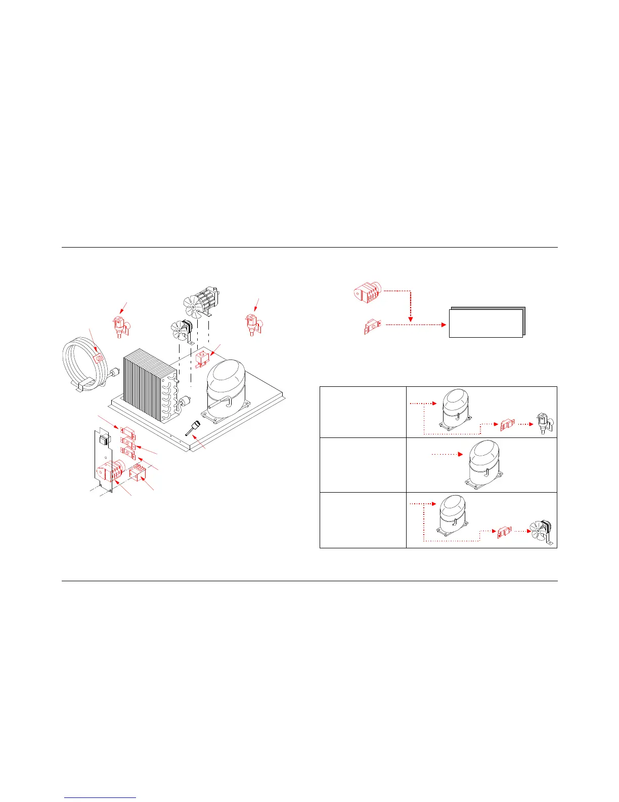
EasyManua.ls Logo

Diamond ICE32A - ELECTRIC CIRCUIT OVERVIEW; WORKING SYSTEM AND UTILIZER UNITS; TIMER AND BIN THERMOSTAT INTERACTION

Diamond ICE32A
48 pages
Print Icon
To Next Page IconTo Next Page
To Previous Page IconTo Previous Page
Loading...
E
E
E
l
l
l
e
e
e
c
c
c
t
t
t
r
r
r
i
i
i
c
c
c
C
C
C
i
i
i
r
r
r
c
c
c
u
u
u
i
i
i
t
t
t
The following diagram shows the main concepts of the electric
circuit:
Compressor
Condenser
Pressure switch
Bin
thermostat
Evaporator
thermostat
Hot gas
valve
Water-inlet
valve
(Evaporator)
Pump
Fan
Water-inlet
valve
(Condenser)
Safety
thermostat
no on CB1565W
Timer
Contactor - ONLY CB1565
H.P. Pressure switch - Only CB1565
The ice maker is energized by the bin thermostat, that stops
machine when the bin is full.
The timer is designed in such a way that it is connected
upstream the bin thermostat during the ice production phase, so
that the ice maker will stop only when the ice production phase
is over.
The following scheme shows this working system:
Timer
Utilizer
Unit
Bin thermostat
Only in the ice
production phase
NB: some components of the electrical circuit (called Utilizer
Units) are always energized and do not depend on the timer
status. See the following table:
W
W
a
a
t
t
e
e
r
r
m
m
a
a
c
c
h
h
i
i
n
n
e
e
s
s
Condenser
pressure-switch
Compressor
Water-inlet
valve
(Condenser)
LINE
C
C
B
B
2
2
4
4
6
6
÷
÷
4
4
2
2
5
5
A
A
i
i
r
r
Compressor
LINE
C
C
B
B
6
6
4
4
0
0
÷
÷
1
1
2
2
6
6
5
5
W
W
a
a
t
t
e
e
r
r
Condenser
pressure-switch
Compressor
fan
LINE
For CB1565 the contactor energized the compressor.