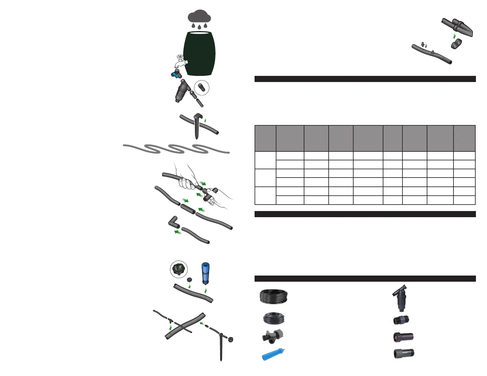
Barrel faucet connections:
Begin the installation at the rain barrel by turning the 3/4″ Y hose
end splitter (optional) onto the male threads of the rain barrel faucet.
Then, connect the 3/4″ plastic screen lter with FHT (#D57A) to one
of the splitter outlets; if the splitter is not used, connect the lter
directly to the rain barrel faucet. Next, force the end of the 1/2″ poly
tubing into the 3/4″ swivel adapter, and then connect the swivel
adapter to the lter outlet by turning it clockwise until hand tight.
Note: If you are connecting this kit to a conventional pressurized outdoor
faucet, install the included pressure regulator (#D46) onto the Y screen-
lter outlet
Drip tubing layout:
Before installing the 1/2″ poly tubing, uncoil the roll and lay it out
in direct sunlight (if possible) for 30 to 40 minutes. This will make it
more pliable and easier to work into the compression ttings during
installation.
Lay out the 1/2″ poly tubing and run it next to as many plants as
possible. Secure the tubing to the soil with the
1/2″ drip tubing stakes. Install the drip tubing in a
gentle S curve to allow for contraction of the 1/2″
tubing at low to high temperatures.
Connect the 1/2″ drip ttings
Use 1/2″ tees (part #C35) and elbows (part #C36) throughout the
layout as needed. To install the 1/2″ compression drip ttings, cut
the drip tubing with a hand pruner, being careful to keep dirt from
entering the line. Hold the tting in one hand and the drip tubing in
the other and force the drip tubing into the compression tting by
moving it from side to side.
Note: Open the faucet on the rain barrel and ush out the poly drip
tubing through the ends before installing the drip emitters.
Drip emitter installation:
The drip emitters can be installed along the poly drip tubing at
varying or specic spacings, depending on the layout of the plants. To
ensure high uniformity, take care not to exceed the recommendations
provided in the chart and the kit specications. Drip emitter ow rate
performance will depend on the rain barrel elevation.
To install the drip emitters, use one of the below options:
Option 1: Installing the drip emitters into the 1/2″ poly tubing
Insert the drip emitters directly into the 1/2″ tubing: Punch a hole
into the side of the poly tubing using the small punch (part #D44).
Snap the barbed side of the drip emitter into the hole after the lines
have been ushed.
Option 2: Installing the drip emitters into the 1/4″ micro tubing
Extend the drip emitters using 1/4” micro tubing to reach plants
that are not near the 1/2″ poly tubing. First, run a length of micro
tubing from the 1/2″ poly tubing to the plant and cut it. Then, insert
a 1/4″ barbed connector (part #H80A) into the micro tubing. Punch a
hole into the 1/2″ poly tubing and insert the 1/4″ barb into the poly
tubing. At the other end of the micro tubing, insert the barbed side
of the drip emitter after the lines have been ushed. Add a stabilizer
stake and secure to the ground.
Initial system start-up
Turn the water on again, ush the line[s], this will ush out any dirt
or debris that may be in the line. Close the end of the poly tubing
with the gure “8” hose end (part #F68B).
Test and inspect the system to identify if there are any leaks in the
drip tubing laterals. If there are any leaks from the barbed ttings or
drip emitters, remove the tting or drip emitters and insert a goof
plug to close the hole. Reinsert the barb tting or drip emitter nearby.
SPECIFICATION
• Operating pressure: 2 to 15 PSI
• Drip emitter ow rates: .5 GPH at 5 PSI,
.8 GPH at 10 PSI, and 1 GPH at 15 PSI (nominal)
• Drip emitter inlet size: 1/4″ barb
Rain
barrel
size
Barrel height
above the
drip sytem
Outlet
pressure
Dripper
ow rate
Length
1/2″ drip
tubing
# of
drippers
Total ow
rate per 50
drippers
Total ow
rate per 50
drippers
Avg.
barrel
time to
empty
60 gal.
227 L
5 ft 2.16 PSI 0.33 GPH Up to 60 ft 50 16.5 GPH .28 GPM 3.6 h
1.5 m .15 bar 1.25 L/H Up to 18 m 50 62.4 L/H 1.04 LPM 3.6 h
60 gal.
227 L
10 ft 4.33 PSI 0.43 GPH Up to 70 ft 50 21.5 GPH .36 GPM 2.8 h
1 m .30 bar 1.62 L/H Up to 21 m 50 81.4 L/H 1.26 LPM 2.8 h
60 gal.
227 L
20 ft 8.66 PSI 0.72 GPH Up to 80 ft 50 36 GPH .60 GPM 1.67 h
6 m .60 bar 2.7 L/H Up to 24 m 50 136 L/H 2.27 LPM 1.67 h
ABOUT THE GRAVITY FEED SYSTEM
In gravity feed systems, raising the rain barrel above the drip system will allow the system to gain
pressure. For every 1′ (30 cm) of elevation above the drip system there is a gain of .433 PSI (.030 bar). If
the rain barrel is raised 10′ (3 m) above the drip system, there is a pressure gain of 4.33 PSI (.30 bar) at
the rain barrel bottom or outlet (.433 x 10 = 4.33).
Keep in mind that low pressure such as 4.33 PSI (.30 bar) or less in a drip system will lead to:
1. Limited distance to the layout of the 1/2″ or 1/4″ drip tubing.
2. Reduction in the drip emitters’ ow rate to considerably below the specied nominal ow rate.
3. A drastic drop in uniformity once a certain length is exceeded.
• Drip emitter outlet side: nipple
• Poly tubing length & size: 100′ of
1/2″ with .600″ ID x .700″ OD
• Micro tubing length & size: 50′ x 1/4″
• Total ow rate for this kit: 32 GPH (.53 GPM)
CONTENTS
(1) 100′ of 1/2″ Black Poly Tubing
with .600″ ID x 700″ OD
part# B36
(1) 50′ of 1/4″ Black Micro Tubing
with .170″ ID x 250″ OD
part# B38P
(1) 3/4″ Y Hose End Splitter
part# D52
(1) Hole Punch
part# D44
(1) 3/4” Filter with FHT x MHT
part# D57A
(1) 3/4″ MPT x MHT Nipple
part# D49
(1) 3/4″ Faucet Adapter
part# C34
(1) 3/4″ Pressure Regulator
part# D46
D52
D57A
C34
D46
3/4” Pressure
Regulator
 Loading...