DRY LOCATION
1 OF 4
IG040617-5.0
DMX DECODER INSTALLATION GUIDE
®
DIMMABLE
12VDC
INSTALLATION GUIDE
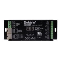
DMX 4-CHANNEL DECODER
24VDC
1. Install in accordance with naonal and local electrical code
regulaons.
2. This product is intended to be installed and serviced by a qualied,
licensed electrician.
3. DO NOT connect directly to high voltage power. Install with a
compable Class 2 constant voltage LED driver (power supply).
4. This product is rated for indoor installaon and is not protected
against moisture.
5. Install appropriately rated wire between driver, decoder, and xture.
When choosing wire, factor in voltage drop, amperage rang, and
type (in-wall rated, etc.) Inadequate wire installaon may cause re.
6. Do not modify or disassemble product beyond instrucons or
warranty will be void.
SAFETY & WARNINGS
QUICK SPECS / MODELS
INSTALLATION
TURN POWER OFF AT CIRCUIT BREAKER
Input Output Max Load
DI-1810
(also DI-1918)
12 - 24VDC 12 - 24VDC
4CH x 5A
4CH x 96W (12V)
4CH x 192W (24V)
SHOCK HAZARD! May result in serious injury or death.
Turn power OFF at circuit breaker prior to installalaon.
DETERMINE LOCATION TO INSTALL COMPONENTS
V+
V-
V+
CH1 - R
CH2 - G
CH3 - B
CH4 - W
0-5 0-9
0-9
Data IN
Data OUT
1) Driver 2) DMX
Controller
3) DMX
Decoder
4) Fixture(s)
CONNECT DECODER TO DRIVER. ATTACH LED
FIXTURE. ONLY USE COPPER WIRING.
Reference SYSTEM DIAGRAM located further in guide for
visual.
CONNECT DECODER TO MASTER DMX
CONTROLLER.
INSTALL ADDITIONAL COMPONENTS, VERIFY
CONNECTIONS, TURN MAIN POWER ON AT
BREAKER.
MAXIMUM DAISY-CHAIN DMX DECODERS
A maximum of 10x DMX Decoders may be connected together via
RJ45 DMX Connecon Ports. DMX signal may be extended further
by installing a DMX 8-Way Splier (DI-1804) aer the 10th DMX
Decoder.