Do you have a question about the Dipl.-Ing. H. Horstmann SMART NAVIGATOR and is the answer not in the manual?
Details regulatory compliance for the SMART NAVIGATOR in the USA, including FCC rules and warnings.
Details regulatory compliance for the SMART NAVIGATOR in Canada, including IC rules and warnings.
States conformity with EC EMC and Low Voltage Directives, and CE Declaration of Conformity.
Overview of the manual's scope, describing the SMART NAVIGATOR Faulted Circuit Indicator for overhead lines.
Lists and defines abbreviations used in the manual for terms like DA, FCI, ISM, RF, and RTU.
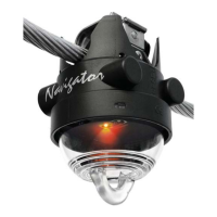
Describes the SMART NAVIGATOR as an overhead fault indicator for Smart Grid Distribution Automation applications.
Details the SMART NAVIGATOR's design for overhead circuits, fault indication via LED and radio, and its role in DA.
Provides a 2D view of the SMART NAVIGATOR, highlighting battery compartments and the TEST contact.
Explains how the SMART NAVIGATOR detects, indicates, and resets faults using an LED and current tracking.
Details the RF communication between SMART NAVIGATOR and SMART RECEIVER using 2.4GHz ISM band.
Describes the two reed contacts (TEST and RESET) activated by a magnet for testing and resetting functions.
Explains the power source for the SMART NAVIGATOR, comprising an internal battery and energy harvesting.
Outlines safety regulations and the use of protective equipment, like hot sticks, during installation.
Provides a step-by-step guide with illustrations for mechanically installing the SMART NAVIGATOR on conductors.
Details the information sent by the SMART NAVIGATOR to the SMART CONTROLLER/RECEIVER regarding events and data.
Guides through the 4-step procedure to register SMART NAVIGATOR units with a SMART RECEIVER.
Presents detailed electrical, transmitter, and mechanical specifications for the SMART NAVIGATOR.
Shows a photograph of the SMART NAVIGATOR and highlights the location of FCC ID and IC ID labels.
| Brand | Dipl.-Ing. H. Horstmann |
|---|---|
| Model | SMART NAVIGATOR |
| Category | Car Navigation system |
| Language | English |