1) Plug the 10 PIN harness into the module. LED will turn ON solid.
2) Turn the ignition key to the ON position. LED will turn off then it will begin a flash pattern that matches the vehicle type selection.
(The default vehicle type selection is Type 1.)
*If the module has already been programmed to the vehicle, LED will flash 4 times. If this happens, skip to step 4.
3) To change the vehicle type, press and release the program button until LED flash pattern matches the selected vehicle type.
LED flash pattern will match the Vehicle Type selected. Example: 1 flash = Type 1, 2 flashes = Type 2 and so on.
4) To save the vehicle type selection, press and hold the program button until the LED flashes rapidly. The module will then exit the
programming. The module is now programmed.*If LED comes on solid, turn the key to start the engine.
The interface kit is designed to operate on any one of 7 possible vehicle types. Once the 10 pin harness wires have been connected,
the next step is to program the interface module to operate on the appropriate vehicle type. *Refer to the Vehicle Type Chart..
VEHICLE TYPE PROGRAMMING:
MODE 1 =
MODE 3 = *OPTION 1
MODE 4 = *OPTION 1
MODE 5 = *OPTION 1
MODE 8 = *OPTION
: (aux2) Pink/White Wire Negative
: (aux2) Pink/White Wire Output
: Window Roll-Up OFF
1: N/A
*OPTION 1 1st Pulse Unlock All Doors:
MODE 2= *OPTION 1: (aux1) Pink Wire Negative
OPTION 2 1st Pulse Unlock Driver Door, 2nd Pulse Unlock All Doors:
OPTION 2: (aux1) Pink Wire Positive
OPTION 2
OPTION 2
OPTION 2
: (aux2) Pink/White Wire Positive
: (aux2) Pink/White Wire Input
: Window Roll-Up ON
OPTION 2: Reset Mode With Unlock Button
* = Default
INSTALLATION NOTES:
!
!
The module will detect all door triggers through the data line. When the module detects an open door through the data line, it will send a negative pulse (-)
trigger on the PURPLE/WHITE wire (Door trigger output).
For Type 1 and 4 vehicles, the front doors and rear hatch ONLY are monitored via the data line. The rear doors are triggered separately and are not
monitored via the data line. You need to use the PINK wire to detect rear doors (Option Programming Mode 2). These wires are usually found at the BCM
(Body Control Module) or at the rear doors.
Section C
Section D
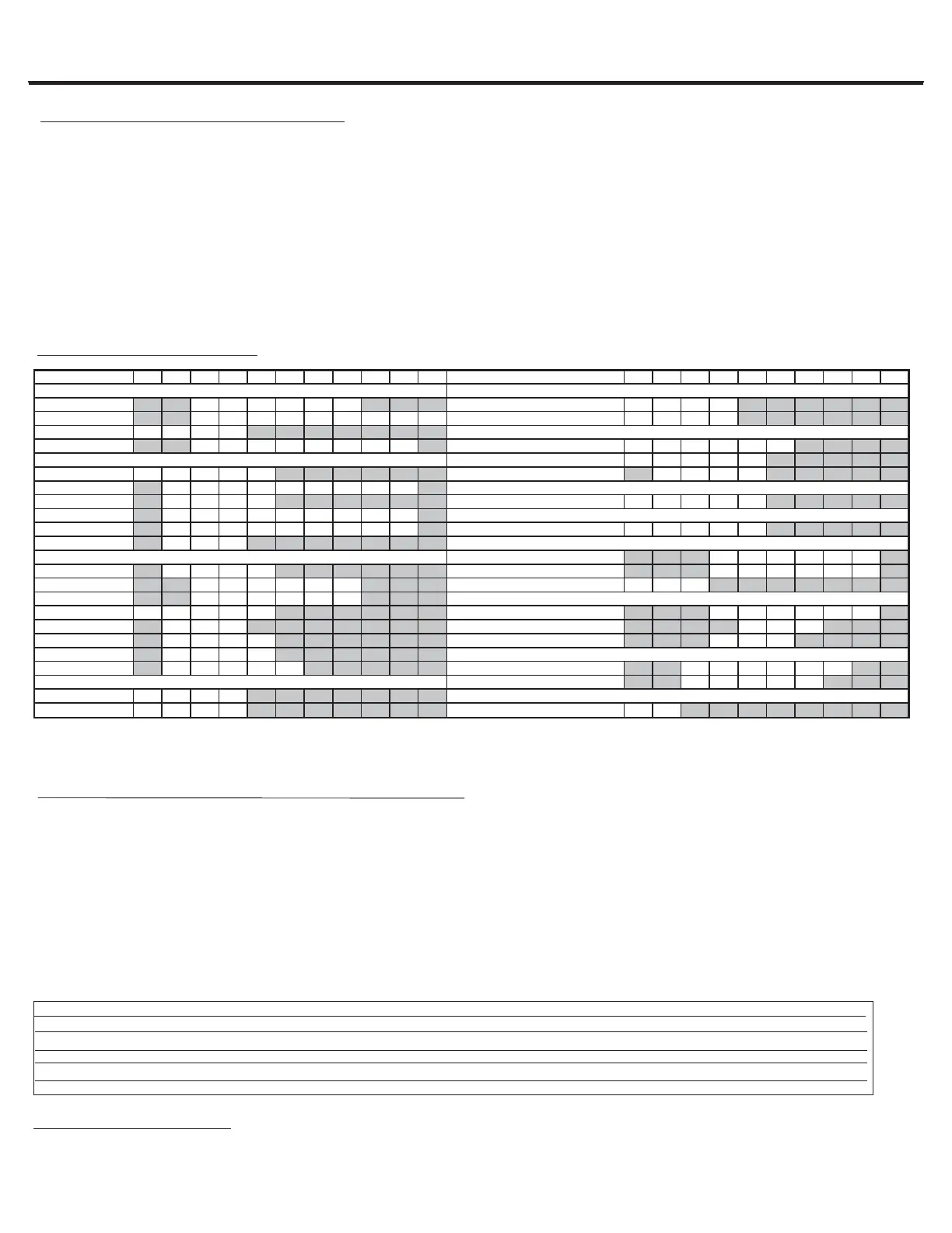
VEHICLE TYPE CHART:
USER SETTINGS - OPTIONAL PROGRAMMING:
USER MODES ARE IDENTIFIED BY A SLOW LED FLASH PATTERN. 1 SLOW FLASH=MODE1, 2 SLOW FLASHES=MODE 2 ETC.
1) Turn the ignition key to the OFF position.
2) To access USER MODES: Press & Hold the programming button until the LED flashes rapidly, then release.
3) To select a MODE: Press & Release the program button until the slow LED flash pattern matches the required MODE selection:
Ex: 1 SLOW flash = MODE 1, 2 SLOW flashes = MODE 2.
4) To change the MODE OPTION: Press the LOCK or UNLOCK button on the aftermarket transmitter.
LED will confirm selection of OPTION 1 with one fast flash or OPTION 2 with two fast flashes and so on.
5) To Save & Exit : Push & Hold the programming button until LED flashes once.
Section E
1700G1
Installation
Manual
(2\3 Pages)
AMERICAN DOOR LOCK INTERFACE
& GM IMMOBILIZER OVERRIDE XK01-AMDL
VEHICLES
2007 2006 2005 2004 2003 2002 2001 2000 1999 1998 1997
VEHICLES
2007 2006 2005 2004 2003 2002 2001 2000 1999 1998
Le Sabre
222222
Caravan
7777
Park Avenue 333333333
Grand Caravan
7777
Rainier
1111
Ultra
33333333
Envoy
111111
Sierra 1500, 2500, 3500 4**
4444
CTS
22222
Yukon Denali
4444
DeVille
322222222
Escalade
4444
H2
44444
Seville SLS
333333222
Seville STS
333333222
Ascender
11111
SRX
222
Grand Cherokee 555555
Avalanche
4444 Grand Cherokee Ltd 555555
*Impala LS *2 *2 *2 *2 *2 *2
Liberty 777
*Monte Carlo *2 *2 *2 *2 *2 *2
Silverado 4**
4444
(with factory remote only) *Alero *2 *2 *2 *2 *2 *2
SSR
111
Aurora
222
Suburban
4444
Bravada
111
Tahoe
4444
TrailBlazer
11111
Bonneville
222222
CHRYSLER
(with factory remote only) *Grand Am *2 *2 *2 *2 *2
Pacifica
6666
Town & Country
7777 9-7X 11
JEEP
OLDSMOBILE
PONTIAC
SAAB
*In some cases the AMDL may only bypass the Passlock II via data. Once programmed, test the door lock inputs to determine if the AMDL will activate these functions via DATA
(multiplexed). If there is no activation, then the door lock system is resistance based and will need to be controlled via analog.
**AMDL can be used only if PIN#2 (Violet Wire) is found at the ODBII connector in vehicle.
BUICK
CADILLAC
CHEVROLET
DODGE
GMC
HUMMER
ISUZU
 Loading...