5
Wiring Earth Ground & Power, see image
6
Warning: Before making power terminations, de-en-
ergize the 24V power source. Do not restore power until
completing all other mounting and wiring. See “Power
up and initial checkout”.
Prerequiste: A nearby earth grounding point.
1
Install the included earth ground wire to the control-
ler’s earth ground spade lug, and terminate the other
end to a nearby earth ground.
2
Unplug the controller’s 2-position power connector
plug and terminate the 24V supply source (AC or
DC) to the connector. Leave connector unplugged for
now.
Power Up and Initial Checkout
Apply power by doing one of the following:
• Insert the 2-position 24V power connector plug, or
• Insert the barrel plug of the wall- mount AC adapter
(WPM-8000).
Check the STAT (Status) and BEAT (Heart- beat) LEDs.
When power is applied, the green “STAT” LED will light.
is indicates the system is OK, with power applied.
During bootup, the “BEAT” LED may blink at 1 Hz with
a 90%/10% on/o duty cycle. When bootup completes,
the platform daemon is started, and the normal 1 Hz
ash at 50%/50% on/ o duty cycle of the “BEAT” LED
returns.
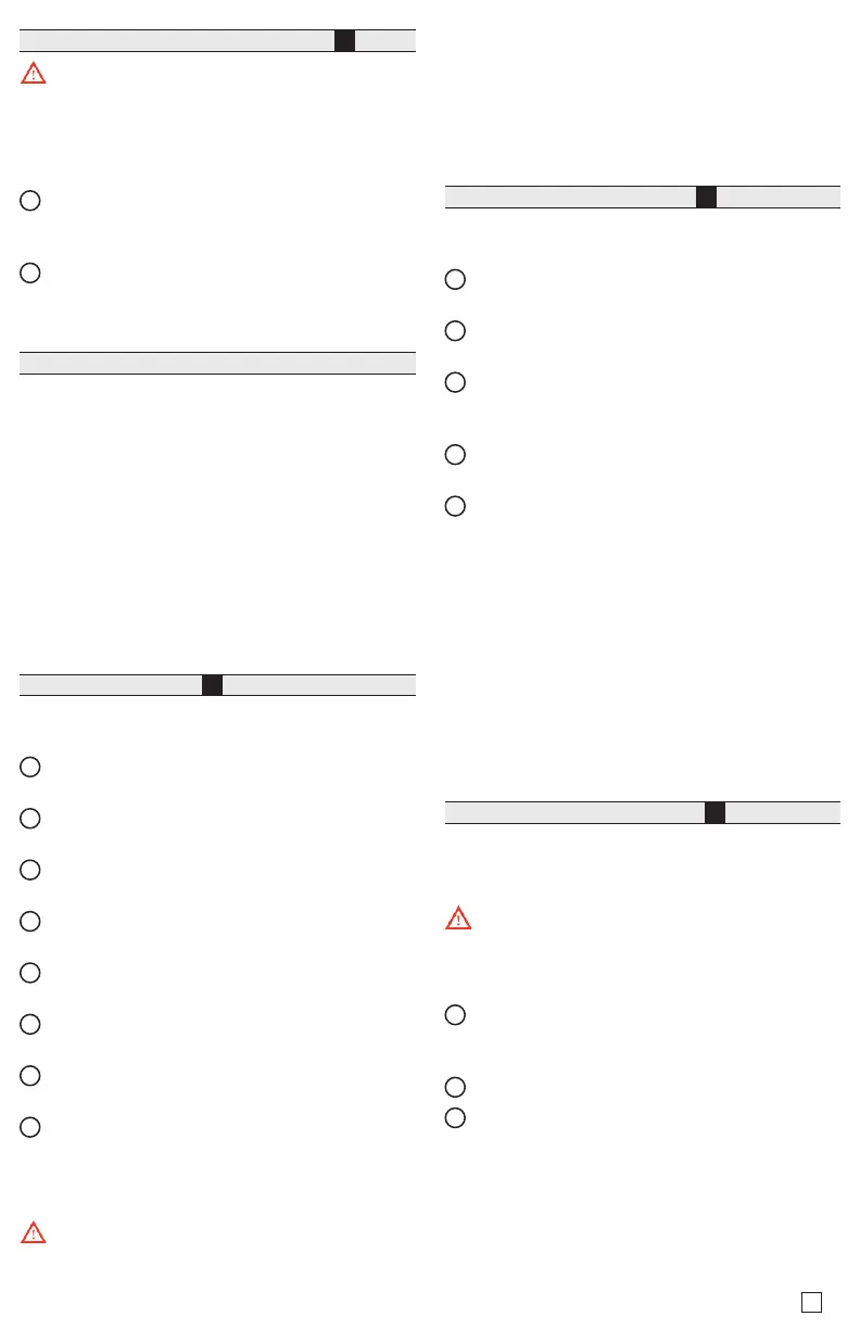
Status LEDs , see image
7
e controller provides a number of status LEDs, with all
but one visible with the front access door closed.
1
WLAN (Green) - Illuminates whenever WLAN
cong switch is not O.
2
RS485 “A” (COM1): Transmit (TX, Yellow) and
Receive (RX, Green).
3
RS485 “B” (COM2): Transmit (TX, Yellow) and
Receive (RX, Green).
4
STAT (Green) - Remains illuminated while controller
is powered.
5
BEAT (Yellow) - “Heartbeat”, normally 1Hz, 50%
duty cycle.
6
Secondary Ethernet, SEC (LAN2) “Link” (Green) and
“Activity” (Yellow).
7
Primary Ethernet SEC (LAN1) “Link” (Green) and
“Activity” (Yellow).
8
(Behind Door) BACKUP - Green, typically O.
If the “BEAT” LED stays illuminated constantly, does not
light, or blinks very fast, contact System Engineering for
technical support.
e 1Hz, 90%/10% on/o “BEAT” ash at bootup
also occurs during other critical operations, such as a
rmware upgrade to the controller and/or any attached
modules. To be safe, do not remove power from the
controller while its “BEAT” LED ashes with a 90%/10%
on/o duty cycle. Wait for the normal (50%/50%) ash
to return before removing power.
For details on the controller’s various LEDs and push-
button switches, see the EC-BOS-8 Mounting and Wiring
Guide.
USB Ports & Switches, see image
8
Behind the front access door are two USB ports, two
pushbutton controls, and an associated LED.
1
PROG - USB 2.0 for usage with USB ash (thumb)
drive.
2
DEBUG - Micro-A USB for serial debug communica-
tions.
3
BACKUP - Pushbutton switch to start a USB backup,
or if held in during power up/boot up, a factory
recovery image.
4
SHT/DWN - Recessed switch for controlled shut-
down.
5
BACKUP - LED to indicate USB media present, or a
backup, restore, or factory recovery image in prog-
ress.
e DEBUG port is a standard Micro-A type USB port
for serial debug communications to the controller. Use a
serial terminal program (for example: PuTTY) to access
the controller “system shell” menu. is provides access
to some basic platform settings.
Default DEBUG port settings are: 115200, 8, N, 1 (baud
rate, data bits, parity, stop bits). For details on using a
serial connection to the DEBUG port, see the EC-BOS-8
Install and Startup Guide.
NOTE: Login requires admin-level platform credentials.
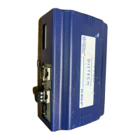
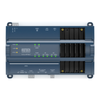
Tab Mounting option, see images
i
DIN rail mounting is recommended. Where tab mount-
ing is required, use dimensions in the illustration to
mount the controller and up to 4 option modules.
Caution: Do not mount hardware on both a DIN
Rail and with tab mounts to another surface. is causes
physical stress on equipment and prevents good connec-
tions between controller and modules.
1
EC-BOS-8 with no option modules added. Allow at
least 1.5” (38mm) clearance around all sides and a
minimum 3” (67mm) at bottom for WLAN antenna.
2
Option expansion module. Up to 4 may be used.
3
Note distances between center of tabs from one unit
to another unit.
More Information
For more information see EC-BOS-8 Mounting and Wir-
ing Guide. For EC-Net Access usage, refer to the
EC-Net
Access Guide
.
EC-BOS-8 Quick Start_IG_12_EN
 Loading...