Wiring
• Deactivate the 24 Vac/dc power supply until all the connections are
done for the device in order to prevent electrical shock or equipment
damage.
• Use 14-22 AWG (2.08 mm
2
to 0.205 mm
2
) shielded wiring for all
connections and do not locate the device wires in the same conduit as
any wiring used to supply inductive loads such as motors. Perform all the
connections in accordance with the applicable national and local codes.
• Provide at least 6” (15cm) of wire into the enclosure, then complete the
wiring connection according to the wire diagram for the applicable power
supply and output signal type.
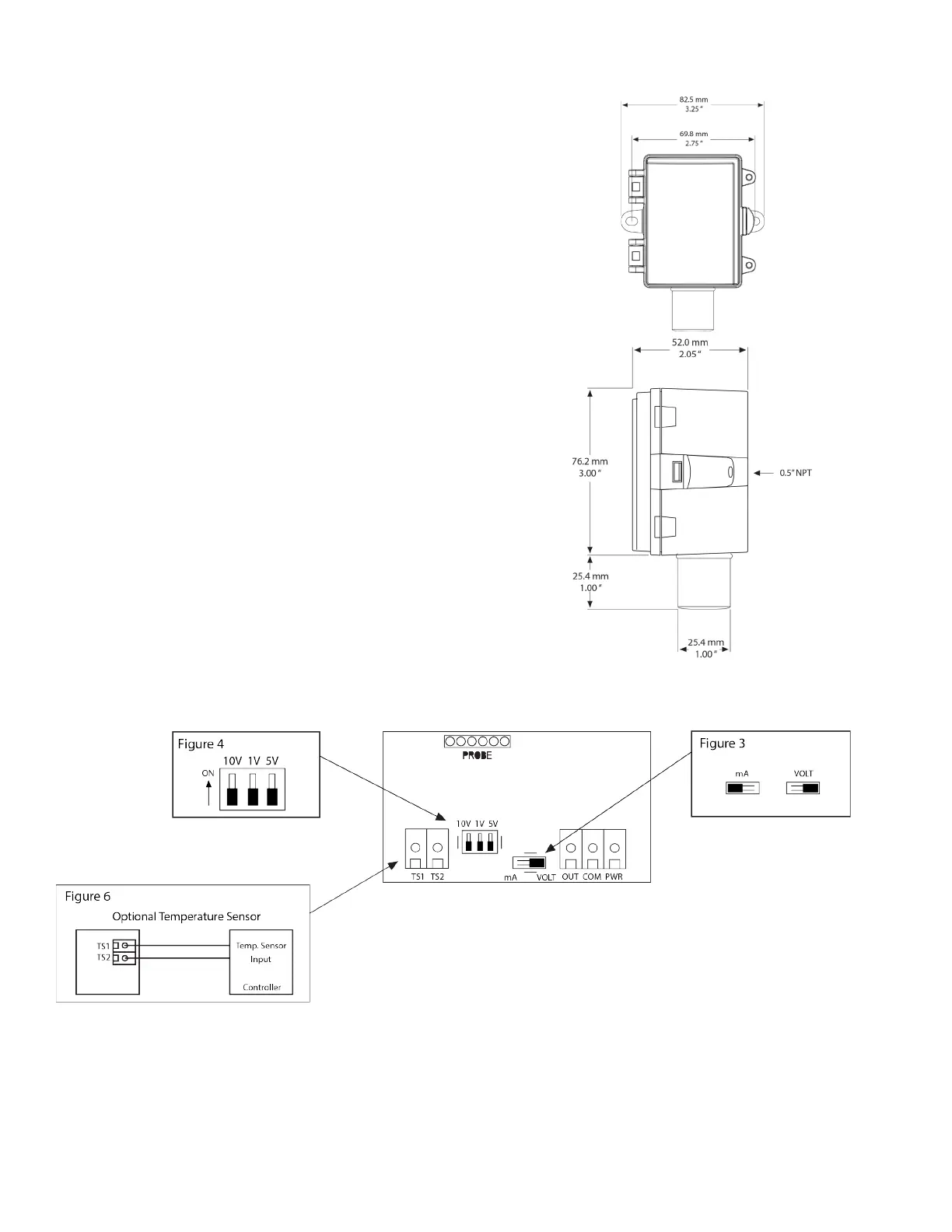
• Select the desired signal output type (mA or Vdc) by placing the output
switch in the required position, as shown in Figure 3. The factory default
is mA (4-20 mA).
• If mA was selected, no further Output set-up is required. If VOLT output
is selected in Figure 3, place the Voltage Output switch to the desired
span position, as shown in Figure 4, i.e. 10 = 0-10 Vdc. The factory
default is 10v = 0-10Vdc.
• Connect the DC positive or the AC voltage hot side to the PWR
terminal. For voltage output or AC power, the Common supply is
connected to the COM terminal. The device is reverse voltage protected
and will not operate if connected backwards. It has a half-wave power
supply, so the Common supply is the same as the Common signal. See
Figure 5.
•The analog output is available at the OUT terminal. Check the controller
Analog Input to determine the proper connection before applying power,
as shown in Figure 4.
• If installed, the resistance temperature output is available at the two
terminals labelled TEMPERATURE SENSOR, as shown in Figure 6.
Dimensions
 Loading...