XR20CE2probecooling XR20C 2/2
• COF Compressor OFF time with faulty probe:
(0÷255 min) time during which the compressor is OFF
in case of faulty thermostat probe. With COF=0
compressor is always active.
DISPLAY
• CF Temperature measurement unit: °C =
Celsius; °F= Fahrenheit. WARNING: When the
measurement unit is changed the SET point and the
values of the parameters Hy, LS, US and Ot have to be
checked and modified if necessary).
rES Resolution (for °C): (in = 1°C; dE = 0.1 °C) allows the
decimal point displaying.
DEFROST
dtE Defrost termination temperature: (-50÷50 °C/
-58÷122°F) (Enabled only when P2P=y) sets the
temperature measured by the evaporator probe, which
causes the end of defrost.
IdF Interval between defrost cycles: (1÷120h) Determines
the time interval between the beginning of two defrost
cycles.
MdF Length for defrost: (0÷255min) It sets the defrost
duration.
• dFd Temperature displayed during defrost: (rt = real
temperature; it = temperature at defrost start; SEt = set
point; dEF = “dEF” label)
• dAd MAX display delay after defrost: (0÷255min).
Sets the maximum time between the end of defrost and
the restarting of the real room temperature display.
DIGITAL INPUT
i1P Digital input polarity: oP: the digital input is activated
by opening the contact; CL: the digital input is activated
by closing the contact.
did: (0÷255 min) door open signalling delay
• odc Compressor status when open door:
no=Digital Input not used CPr= Compressor OFF.
OTHER
rEL Software release for internal use.
Ptb Parameter table index: readable only. For internal use.
7. DIGITAL INPUT
7.1 DIGITAL INPUTS POLARITY
The digital input polarity depends on the “i1P” parameter.
i1P=CL: the input is activated by closing the contact.
i1P=OP: the input is activated by opening the contact
8. INSTALLATION AND MOUNTING
Instrument XR20C shall be mounted on panel, in a 29x71
mm hole, and fixed using the special brackets supplied.
To obtain an IP65 protection grade use the front panel rubber
gasket (mod. RG-C) as shown in figure.
The temperature range allowed for correct operation is 0÷60
°C. Avoid places subject to strong vibrations, corrosive
gases, excessive dirt or moisture. The same
recommendations apply to probes. Let air circulate by the
cooling holes.
9. ELECTRICAL CONNECTIONS
The instruments are provided with screw terminal block to
connect cables with a cross section up to 2,5 mm
2
. Heat-
resistant cables have to be used. Before connecting cables
make sure the power supply complies with the instrument’s
requirements.
Separate the probe cables from the power
supply cables, from the outputs and the power
connections. Do not exceed the maximum current allowed
on each relay, in case of heavier loads use a suitable
external relay.
9.1 PROBE CONNECTION
The probes shall be mounted with the bulb upwards to
prevent damages due to casual liquid infiltration. It is
recommended to place the probe away from air streams to
correctly measure the average room temperature.
10. HOW TO USE THE HOT KEY
10.1 HOW TO PROGRAM A HOT KEY FROM THE
INSTRUMENT (UPLOAD)
1. Program one controller with the front keypad.
2. When the controller is
ON, insert the “Hot key” and
push o key; the "uPL" message appears followed a
The word “End”
3. Push “SET” key and the End will stop being displayed.
4.
Turn OFF the instrument remove the “Hot Key”, then
turn it ON again.
NOTE: the “Err” message is displayed for failed
programming. In this case push again o key if you want to
restart the upload again or remove the “Hot key” to abort the
operation.
10.2 HOW TO PROGRAM AN INSTRUMENT
USING A HOT KEY (DOWNLOAD)
1. Turn OFF the instrument.
2. Insert a programmed “Hot Key” into the 5 PIN
receptacle and then turn the Controller ON.
3. Automatically the parameter list of the “Hot Key” is
downloaded into the Controller memory, the “doL”
message is blinking followed a by “End”.
4. After 10 seconds the instrument will restart working
with the new parameters.
5. Remove the “Hot Key”.
NOTE the message “Err” is displayed for failed programming.
In this case turn the unit off and then on if you want to restart
the download again or remove the “Hot key” to abort the
operation.
11. ALARM SIGNALS
Message Cause Output
“EE” Data or memory failure
“P1”
Room probe failure Output according to par.
“Con” and “COF”
“P2”
2
nd
probe failure Output unchanged
“dA” Door open Regulation restarts
11.1 ALARM “EE”
The instrument is provided with an internal check verifying
memory integrity. Alarm “EE” flashes when a failure in the
internal memory is detected. In such case call the service.
11.2 ALARM RECOVERY
Probe alarm “P1 & P2” start some seconds after the fault in
the related probe; it automatically stops some seconds after
the probe restarts normal operation. Check connections
before replacing the probe.
Alarm dA will recover as soon as the digital input is disabled.
12. TECHNICAL DATA
Housing: self extinguishing ABS.
Case: XR20C frontal 32x74 mm; depth 60mm;
Mounting
XR20C panel mounting in a 71x29mm panel cut-out
Protection: IP20.
Frontal protection:
XR20C IP65 with frontal gasket RG-C (optional).
Connections: Screw terminal block ≤ 2,5 mm
2
heat-
resistant wiring.
Power supply: according to the model: 12Vac/dc, ±10%;
24Vac/dc, ±10%; 230Vac ±10%, 50/60Hz, 110Vac ±10%,
50/60Hz
Power absorption: 3VA max
Display: 3 digits, red LED, 14,2 mm high.
Inputs: 2 NTC probes. 1 Digital input
Relay outputs
Compressor:
SPST relay 16FLA/96LRA
Data storing: on the non-volatile memory (EEPROM).
Kind of action: 1B.
Pollution grade: normal
Software class: A.
Operating temperature: 0÷60 °C.
Storage temperature: -25÷60 °C.
Relative humidity: 20÷85% (no condensing)
Measuring and regulation range:
NTC probe: -40÷110°C (-58÷230°F)
Resolution: 0,1 °C or 1°C or 1 °F (selectable).
Accuracy (ambient temp. 25°C): ±0,7 °C ±1 digit
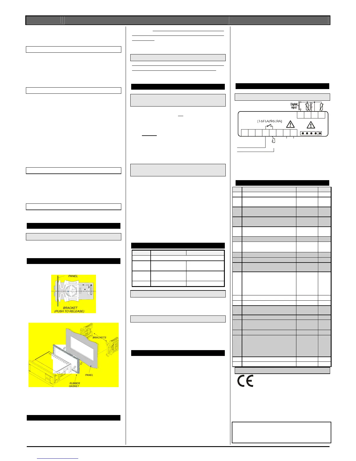
13. CONNECTIONS
13.1 XR20C: 16FLA COMPRESSOR
456 7
9101112
Comp
Room
8
Hot Key
Line
Supply
120V~
120Vac supply: connect to the terminals 7 and 8.
OPTIONAL:
12Vac/dc supply: connect to the terminals 7 and 8.
24Vac/dc supply: connect to the terminals 7 and 8.
230Vac supply: connect to the terminals 7 and 8.
14. DEFAULT SETTING VALUES
Label Name Range °C/°F
Set
Set point LS÷US
3/37
Hy
Differential
0,1÷25.5°C/
1÷ 45°F
2/4
LS
Minimum set point
-50°C÷SET/
-58°F÷SET
-40/
- 40
US
Maximum set point
SET÷150°C/
SET ÷ 230°F
110/
230
Ot
Thermostat probe calibration
-12÷ 12°C /
-21 ÷ 21°F
0/0
P2P
2
nd
probe presence Y/N
Y
OE
2
nd
probe calibration
-12÷12°C /-
120÷120°F
OdS
Outputs delay at start up 0÷255 min
0
AC
Anti-short cycle delay
0 ÷ 50 min
1
COn
Compressor ON time with faulty
 Loading...