Do you have a question about the DL Manufacturing Smart Chock SC0650 and is the answer not in the manual?
Overview of the Smart Chock™ Installation Guide for models SC650-SC654.
System behavior during normal operations: door open/close, chock removal, and status lights.
System responses to critical safety events like premature chock removal or door opening without chock.
Lists essential tools needed for the installation process, including drills and wrenches.
Outlines recommended annual checks for proper system functioning and longevity.
Details mounting hardware and fasteners supplied by the installer for different mounting surfaces.
Lists other necessary materials like wiring and conduit for installation.
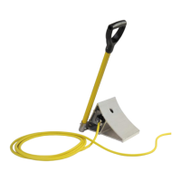
Step-by-step instructions for attaching the standard chock handle assembly using provided hardware.
Instructions for attaching the vector chock handle assembly with specific torque requirements.
Detailed steps and dimensions for mounting the internal yellow Smart Chock™ box.
Further instructions and diagrams for mounting the inside light box on walls.
Instructions for installing the photo eye above the door for typical and MxV doors.
Guidance on connecting the photo eye and adjusting its sensing distance for proper operation.
Steps for mounting the magnetic sensor on rolling steel doors at the recommended height.
Details on connecting the magnetic sensor to the control board's 'DOOR' connector.
Steps for attaching the outside components, including the pole, to the wall.
Overview of terminal block connections and their functions on the control board.
Details on optional terminal block jumpers, sensors, and alternate contacts.
Diagram showing the field wiring for incoming power to the internal yellow box.
Diagram illustrating the wiring for the door photo sensor, including sensing reversal.
Wiring for the leveler control signal and fan behavior when the button is pressed.
Wiring for leveler interlock and OPT1 contacts rated for 120 VAC.
Diagram showing connections between the outside light box and the inside control board.
Details on terminal block configurations for red versus amber icon boards.
Terminal identification for the chock cable plug and socket on the outside light box.
Wiring colors and terminal assignments for the Pollack electrical cord.
| Brand | DL Manufacturing |
|---|---|
| Model | Smart Chock SC0650 |
| Category | Automobile Accessories |
| Language | English |