Do you have a question about the DMP Electronics XR350 and is the answer not in the manual?
This document outlines the procedures for arming and disarming the XR100/XR500 or XR150/XR350/XR550 alarm systems, along with a visual guide to the keypad layout and its functions.
To disarm the alarm system, follow these steps:
CMD button on the keypad until the display shows "ARM DISARM".DISARM option. You will then be prompted to enter your personal user code, followed by pressing CMD to confirm.NO, the keypad will sequentially display the name of each armed area, followed by "NO YES". You can then choose YES or NO for each individual area to disarm only specific areas of your choice.YES, all armed areas will be disarmed.To arm the alarm system, follow these steps:
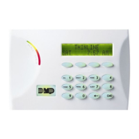
CMD button on the keypad until the display shows "ARM DISARM".ARM option. If a closing code is required, you will be prompted to enter your user code, followed by pressing CMD to confirm.NO, the keypad will sequentially display the name of each area, followed by "NO YES". You can then choose YES or NO for each individual area to arm only specific areas of your choice.YES, all areas will be armed.The keypad features a 32-character display that shows system status, time, and messages. It includes several indicator lights and a numeric keypad for data entry.
The keypad also features dedicated shortcut keys for common functions, often labeled with icons or specific text:
The document includes flowcharts illustrating the disarming and arming processes:
NO is selected: "Select NO to Disarm only certain areas."YES is selected: "Select YES to Disarm All."NO is selected: "Select NO to Arm only certain areas."YES is selected: "Select YES to Arm All."While not explicitly detailed as "maintenance features," the design of the system implies certain aspects that contribute to its upkeep and reliability:
The system is designed, engineered, and assembled in the USA, suggesting a focus on quality control and potentially easier access to support and parts if maintenance or repairs are needed.
| Remote Control | Yes |
|---|---|
| Power Consumption | 25VA |
| Operating Temperature | -10°C to +55°C |
| Humidity | Up to 95% non-condensing |
| Compatibility | DMP Wireless Devices |