5
STEP 9: WITH THE ELECTRICAL POWER OFF, route
#14 gauge stranded copper wire from 12 VDC ground
and positive 12 VDC from the fuse panel through a 2-amp
fuse or circuit breaker. Leave at least 12 inches (305 mm)
of wire for connecting to toilet (g. 9).
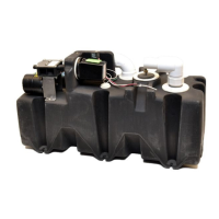
STEP 10: Connect the holding tank to the bottom of the
discharge ange.
STEP 11: Slide the four T-bolts into the slots of the oor
ange. Install the ange gasket over the T-bolts (g.
10).
Fig. 9
Fig. 10
STEP 12: Install oor ange adapter with words “THIS SIDE
UP” facing up. Tighten adapter to oor ange using four
at washers and hex nuts. Tighten in criss-cross pattern
(g. 11).
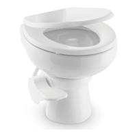
STEP 13: Temporarily set the toilet in place on the oor
ange (g. 14).
STEP 14: Mark the holes for the two toilet mounting
bolts (g. 15).
Fig. 16
STEP 15: Pick up toilet and set aside. Drill 3/16-inch
pilot holes in the oor (g. 16).
Fig. 15
STEP 16: With toilet close to oor ange, connect ex-
ible water supply hose to the water line tting (g. 17).
Fig. 11
Fig. 17
IMPORTANT: If replacing an existing toilet with 2-bolt
oor ange, drill two 5/16-inch dia. holes in old oor
ange that align with two additional holes in oor
ange adapter. Use two #10 or 12 x 1-1/2-inch wood
screws and washers for these drilled holes, and two
T-bolts with at washers and nuts to fasten ange
gasket and oor ange adapter to old oor ange.
Do not use old hardware or seal.
Fig. 14
 Loading...