15
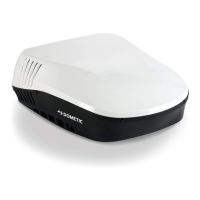
FIG. 29
Do Not Slide
Lift And Place
Front
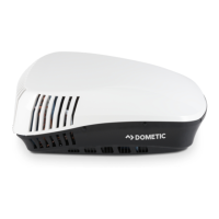
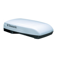
Unit May Vary In Appearance
Model
H540315
H540316
Shown
2. Remove shroud.
3. Align four (4) Dometic cubes with base pan as
shown. See (FIG. 30).
Dometic cubes ensure proper foam block
compressionofapproximately1-1/6″.
Dometic
Cube
(X 4)
FIG. 30
Front
4. Maintaining alignment, place Dometic cubes be-
neath edge of base pan. See (FIG. 30), (FIG. 31)
& (FIG. 32).
FIG. 31
Front
Dometic Cubes
FIG. 32
Front
Dometic Cubes
5. Locate mounting holes in base pan.
6. Pre-drill the mounting holes in roof with 15/64"
bit with a drill gun using a depth gauge.
Do NOT drill without depth gauge to en-
sure bit does NOT penetrate cold air duct.
7. Match3″lagwithbondedsealingwasher.
8. Drivescrewusing9/16″socket.Finishinstalla-
tion with socket until base pan is lightly seated
on Dometic cubes. See (FIG. 30).
Tighten mounting bolts to achieve
proper foam block compression. Overtightening
could damage unit’s base pan. Under tighten-
ing will allow an inadequate roof seal, and could
cause a leak.
Proper compression is achieved when
foam blocks compress to approximately
1-1/6″ so that Dometic cubes no longer
move freely beneath the base pan. There
should be slight resistance between Do-
metic cubes and base pan upon attempt-
ed removal of cubes.
FIG. 33
Dimensions Are Nominal
1-1/6″
INSTALLATION INSTRUCTIONS
 Loading...