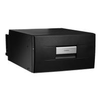
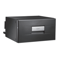
CD20, CD30 Installation
11
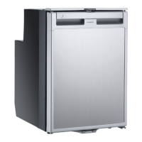
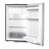
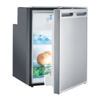
5.1 Control elements
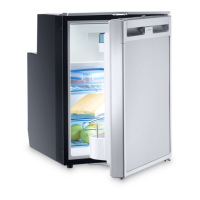
6 Installation
A
I
Please observe the following instructions:
➤ Determine the required cross section of the cable in relation to the cable length
according to fig. 6, page 5.
Key to fig. 6, page 5
Connect your cooling device as directly as possible to the battery terminal or to
an outlet with a fuse rated for at least 15 A (12 V) or 7.5 A (24 V).
➤ Fix the device in place using the screwing holes:
– CD20, see fig. 4, page 4.
– CD30, see fig. 5, page 5.
No. in
fig. 3, page 4
Explanation
1 Thermostat
NOTICE!
• Ensure that the positive cable is connected to the positive terminal
and the negative cable to the negative terminal.
• When choosing the installation location, ensure that the air heated
by the liquefier can be drawn off.
NOTE
• To avoid voltage loss and therefore a drop in performance, the cable
route should be kept as short as possible and should not
be interrupted if this is possible. For this reason avoid additional
switches, plug or power strips.
• You can detach the compressor from the cooling device and mount
it in another place on the cooling device, or separately from it
(fig. 2, page 3). Make sure that the refrigerant line is 1.5 m (59 in).
Co-ordinate axis Meaning Unit
l Cable length m
∅ Cable cross section mm²
CD20-30-IO-US.book Seite 11 Montag, 29. Mai 2017 4:41 16
 Loading...