7
EN
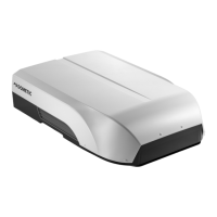
Rooop Air Conditioner (Air Distribution Box, Electronic Controls) General information
4.5 ADB component dimensions
This section provides the internal dimensions of the ADB
component.
q
t
y
w
rr
ee
rr
uu
ii
ii
oo
a
uu
3 Dimension measurements
q
Front of unit
y
Center line of unit
w
2.3 in. (58 mm)
u
11.6 in. (295 mm)
e
23.0 in. (584 mm)
i
3.4 in. (86 mm)
r
20.4 in. (518 mm)
o
6.0 in. (152 mm)
t
Roof opening
a
3.0 in. (76 mm)
4.6 Placement requirements
This section describes factors to consider when placing
the rooop component.
4.6.1 Planning the rooop location
The rooop component is specifically designed for
installation on the roof of an RV. To determine where to
place the rooop component, consider these items.
• A 14.3 in. x 14.3 in. (363 mm x 363 mm)
[±0.1in.(3mm)] square opening and hereinaer
referred to as “roof opening” is required. The
roof opening is part of the return air system of
the rooop component and must be finished in
accordance with NFPA 1192.
• The raer/joist support frames must be spaced
no greater than 16.0 in. (406 mm) on center. The
rooop component is designed to fit over an existing
roof vent opening.
• The distance between the roof and the RV ceiling
must be between 1.5 in. (38 mm) and 6.0 in.
(152mm).
• When no roof vent is available or when another
location is desired, an opening must be cut through
the roof and ceiling of the RV. This opening must
be located between the roof reinforcing members.
Consider these recommendations along with your
cooling needs:
– For a single rooop component: mount the
rooop component slightly forward of the RV’s
center (front to back) and centered from side to
side.
– For two rooop components: measuring from
the front of the RV and centering from side
to side, mount the first rooop component
at 1/3 the length of the RV and the second
rooop component at 2/3 the length of the RV.
4.6.2 Tilt requirements
When measuring for placement, perform the following
actions:
1. Make all measurements while the RV is parked on a
level surface.
2. Install the rooop component on a flat and level roof
section.
3. Use the tilt allowance table to determine the
maximum acceptable roof tilt.
Tilt allowance
Model number Maximum tilt (all directions)
FreshJet 3 series
FreshJet 4 series
15°
 Loading...