14
4.3 Installing the ventilation system
Fig. 11
Minimum height of ventilation
H
Fig. 12
Cut two rectangles in
the exterior wall of the
vehicle.
1
Fig. 13
Seal the mounting
frame making it water-
proof (
does not apply
for mounting frames
with integral seal)
and
screw into position.
2
Fig. 14
Insert ventilation grille.
3
Fig. 15
Install locking slider.
4
Fig. 16
Lock ventilation grille.
5
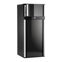
4.3.1 Installation LS300 or L500 (NZ)
b
a
14 x
Installation of lower and upper ventilation
grilles LS300 (or L500 NZ).
Correct mounting of the lower ventilation gril-
le facilitates access to the connections and
functional parts during maintenance.
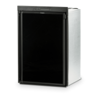
An installation other than described will
reduce the cooling capacity and jeopardi-
se the manufacturer's warranty/product
liability.
CAUTION!
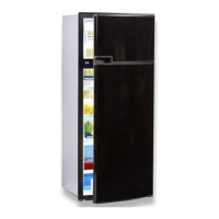
To install the ventilation grilles cut two rectan-
gles to suit vents in the outer wall of the vehi-
cle (for position of the cuts, see Fig. 13).
optional ventilation
aperture Ø min 40 mm
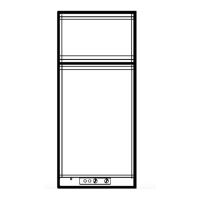
The bottom of the upper ventilation grille must
be equal to or above the height of the refrige-
rator.
Installation
New Zealand only: Please be aware that the
L500 vent grille is equipped with locking
screws instead of sliders.
LS300
or
L500
(NZ)
LS300
or
L500
(NZ)
Flue kit
3776
A
i
i
 Loading...