Circuit Diagrams of Electrical Appliances
21-116
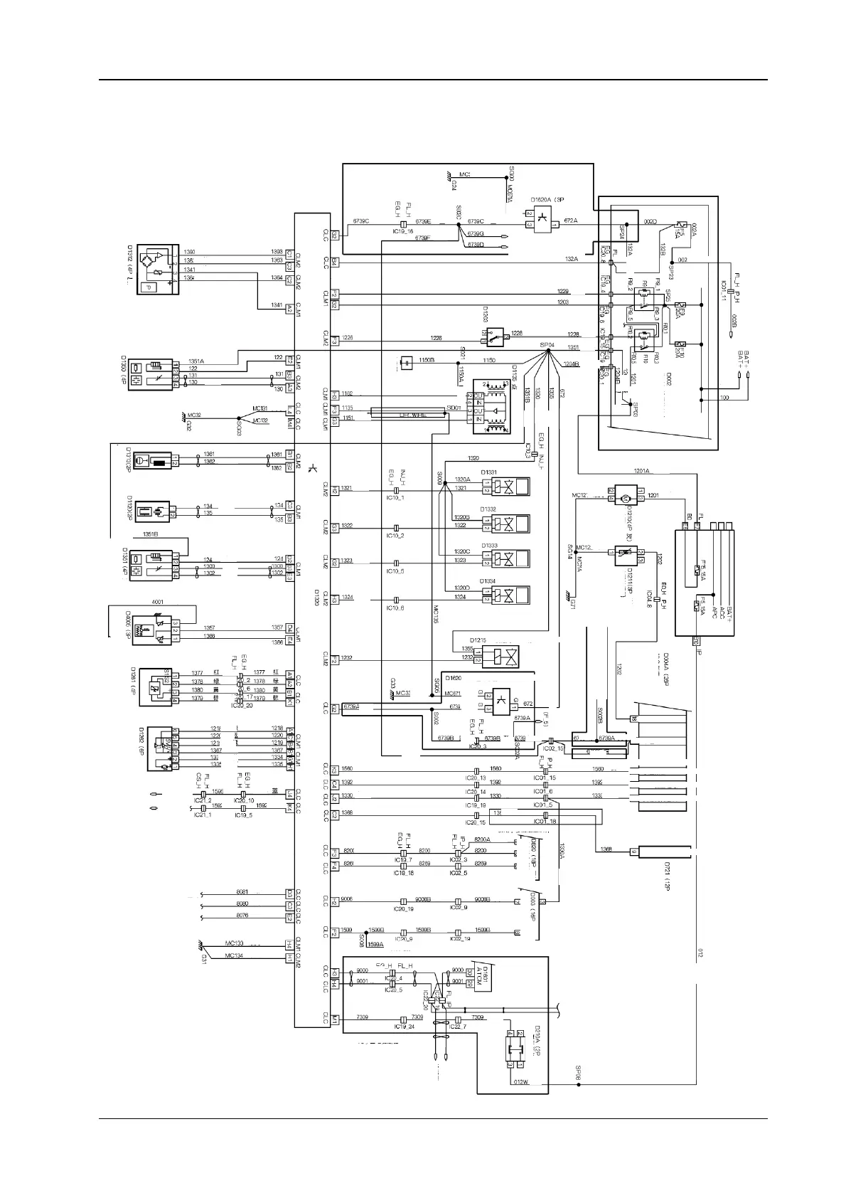
3.3 The electrical location diagram for the engine control S30/H30 (It is applicable to the 6
digits 015982after code ≤VIN <037670)
transmission
***It is used for automatic
Yellow green
The vehicle
speed sensor
Blue
Blue
Blue
Blue
Blue
Blue
Blue
Green
Green
Green
Green
Green
Green
Green
Green
Green
Green
Green
Green
Green
Blue
Blue
Blue
Blue
Green
Green
Green
Green
Green
Green
Green
Green
Green
Blue
Blue
Green
Green
Green
Green
Green
Green
Red
White
Yellow
Gre
Yellow
Black
Yellow
Yellow
Yellow
Yellow
Yellow
Yellow
Yellow
Green
Blue
Blue
Yellow
Yellow
Yellow Yellow
Gre
Red
Brown
Red
Red
Brown
Brown
Brown
Red
Red
Red
Green
Red
Brown
Brown
Brown
Yellow
Brown
Brown
Brown Brown
Brown
Red
Red
Red
Red
Red
Red
Brown
Red
RedRed
Red
Gre
Yellow
Gre
Brown
Brown
r
Green
ellow
Gre
Green
Green
ellow
Green
ellow
Red
Green
Blue
Green
yellow
Green
yellow
Yellow
Brown
Green
yellow
Red
Gre
Grey
Brown
Green yellow
Yellow
green
Yellow
green
Yellow green
Yellow
green
Green
yellow
The cabin fuse box(F5)
To the automatic transmission
control module (B25)
The front oxygen sensor
Green)
Intake air pressure
temperature sensor
Grey)
The inertia
switch
(3P Black)
The capacitor
Engine rotation
sensor
Black) Black)
Blue)
Blue)
Black)
Black)
Red
The fuel nozzle 1
The fuel nozzle 2
The fuel nozzle 3
The fuel nozzle 4
White
The explosion and
vibration sensor
Ignition coil (grey)
The engine
compartment fuse
The back oxygen
sensor
Engine water
m
r
r
n
r
The combined
instrument (blue)
The accelerator pedal
n
r
Air damper
The fan rela
hi
h s
eed
The fan rela
low s
eed
The engine
coolin
The engine
coolin
The electric
enerator com
uter
Carbon tank valve
2P Brown
Gre
The fuel
meter
The oil
meter
Brown)
Blue)
Automatic air conditioning
control module multiple
functional display screen
The combined
instrument
Black)
Black)
Black)
The vehicle s
eed senso
3P white
***It is only used for
automatic air conditioning
The cabin fuse box
***It is used for
manual operated
***It is onl
used for automatic o
erated air conditionin
*** It is onl
used for multi
le functional dis
la
screen
The ft protection
Diagnostic apparatus
The fuel mete
The s
eedomete
The water tem
erature alarm
The OBD ala
m information
The
enerator s
eed mete
The oil consum
tion information
The combined
instrument
Multiple functional
dis
la
screen
Black Brown)
The brake switch
***It is used for automatic
The coolin
fan
White
Grey
Pink
The battery
The ignition switch
o
eration
The cabin fuse box
Yellow
Diagnostic
Diagnostic
Air conditionin
Air conditionin
Air conditionin
 Loading...