Maintenance of electrical applicances
22-56
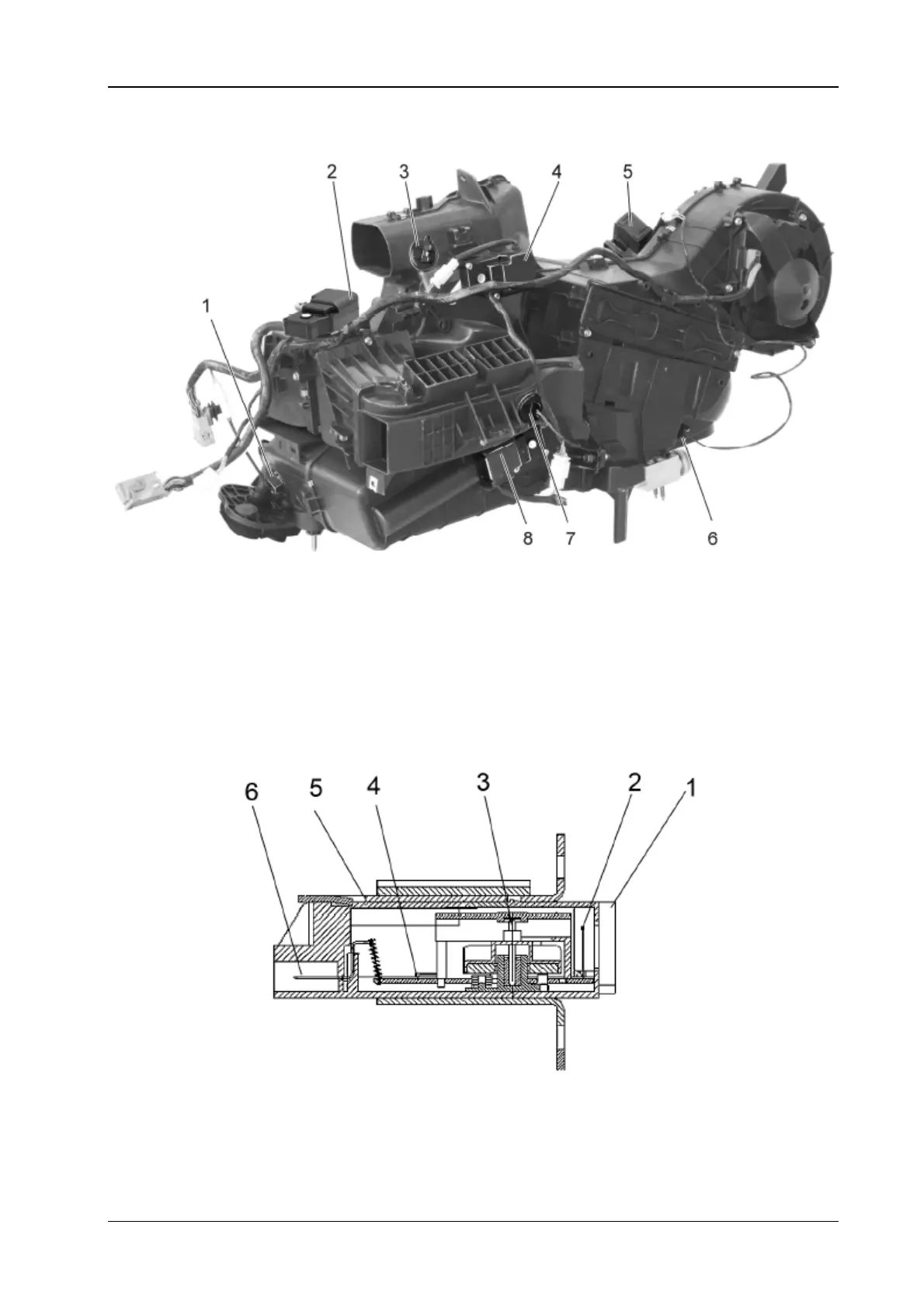
6. The automatic air conditioning
6.1 The structure for the air conditioning assembly
1. The water temperature sensor 2. Foot blowing and defrosting servo motor 3. The face uptake temperature
sensor (T-out 1) 4. The face blowing servo motor 5. The inner and outer cycling servo motor 6. The
evaporator temperature sensor 7. The foot uptake sensor
Fig. 6.1 The chart for the automatic air conditioning assembly
(1) The indoor temperature sensor
The indoor temperature sensor is installed near the instrument panel at the front row, located at the
opposite of the auxiliary driver seat, for delivering the information of air temperature inside the vehicle
to the computer, so that the computer shall conduct the management over the mixing and air flow
distribution and recycling and other functions. It is a piezoelectricity resistance type sensor, the power
is supplied by 5V DC electricity.
1. The sealing strip 2. The thermistor 3. The fan blade combination 4. The circuit board
5. The bracket case 6.The plug connector
Fig. 6.2 The structure for the indoor temperature sensor
 Loading...