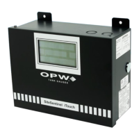
To prevent the possibility of explosion or fire, do not test the sensor in the
Hazardous Area.
Work in a well-ventilated area with no hot surfaces or open flames.
Do not use fuel to test the sensor!
If the Sensor is Installed in a Normally DRY Well
• Place the LOWER float in its UPPER position and the UPPER float in its LOWER position. This should
trigger a low-level alarm in the Controller.
• Place the LOWER float in its UPPER position and the UPPER float in its UPPER position. This should
trigger a high-level alarm in the Controller.
• Return BOTH floats to their LOWER positions and check that the Controller is no longer in the alarm
state.
If the Sensor is Installed in a Normally WET Well
• Place the LOWER float in its LOWER position and the UPPER float in its LOWER position. This should
trigger a low-level alarm in the Controller.
• Place the LOWER float in its UPPER position and the UPPER float in its UPPER position. This should
trigger a high-level alarm in the Controller.
• Place the LOWER float in its UPPER position and the UPPER float in its LOWER position. Confirm that
the Controller is no longer in an alarm state.
If the Controller fails to register the alarm condition, check your programmed thresholds in the Controller.
Check the orientation of the lower float as described on page 29.
Disconnecting the sensor should trigger a high-level alarm. Shorting the sensor should generate a low-level
alarm; check all wiring and junction boxes to ensure continuity without shorts.

 Loading...