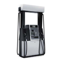
6.11 Product Tube Replacement - Not Using the Tube Removal Tool
This procedure must be used if the tube removal service tool cannot be used or is not
available.
In addition to removing the side columns, this procedure requires removing the valance and the
top plate of the dispenser to gain access to the hose outlet casting and the tube retaining clip
underneath the casting.
Note!
Screws are not used to secure the upper column cover. It snaps into place. Do not use tools to
remove this cover. The proper way to remove the cover is to press with one hand in the middle
at the base and use other hand to unsnap the bottom edge.
1
Trip the emergency shear valve.
2
Run a sale to drain line and relieve pressure.
3
Turn off power to the dispenser and submersible pump at the circuit breakers inside the
building.
4
Place container under the proportional valve to catch fuel.
5
Remove tube retainer pin from valve and pull down on product tube to disconnect it from
valve. See Fig 6.17.
6
Remove hose from the outlet.
7
Remove the upper column cover as follows:
While pressing in the middle of the panel at the base to expand it around the edges, firmly
pull edge of panel straight out to unsnap it. See Fig 6.18 and Fig 6.19.
Note: Removing Upper Column covers. Screws are not used to secure the upper column
cover. It snaps into place. Avoid using tools to remove this cover. The proper way to remove
the cover is to press with one hand in the middle at the base and use other hand to unsnap
the bottom edge.
8
Remove (6) 10 mm screws securing the lower side column cover and lift cover up and remove.
See Fig 6.20.
9
Put tape around the four corners of the valance. This will help keep the valance together so
it can be removed in one piece.
10
Put flat blade screwdriver up under the end valance cover, locate tabs and spread tabs outward
to remove cover. See Fig 6.24.
11
Remove 2 screws on end valance and let valance rest on the hooks.
12
Repeat steps for opposite end of valance and remove the valance.
13
Slide off and remove dispenser top cover plate. See Fig 6-18.
14
Remove 10 mm nuts on outlet casting. (1 nut on outer edge of casting and, depending on
number of products, remove 2, 4 or 6 nuts on casting).
15
Lift casting up and set aside.
100 WM048523 Rev 08 01/2019
6 Replacement Procedures

 Loading...