All rights reserved. Copyright reserved.
_ _Printed on_18.05.05_F61733XXT01.fm
16
Dräger Medical AG & Co. KGaA 6173.3
Function description Babylog 8000
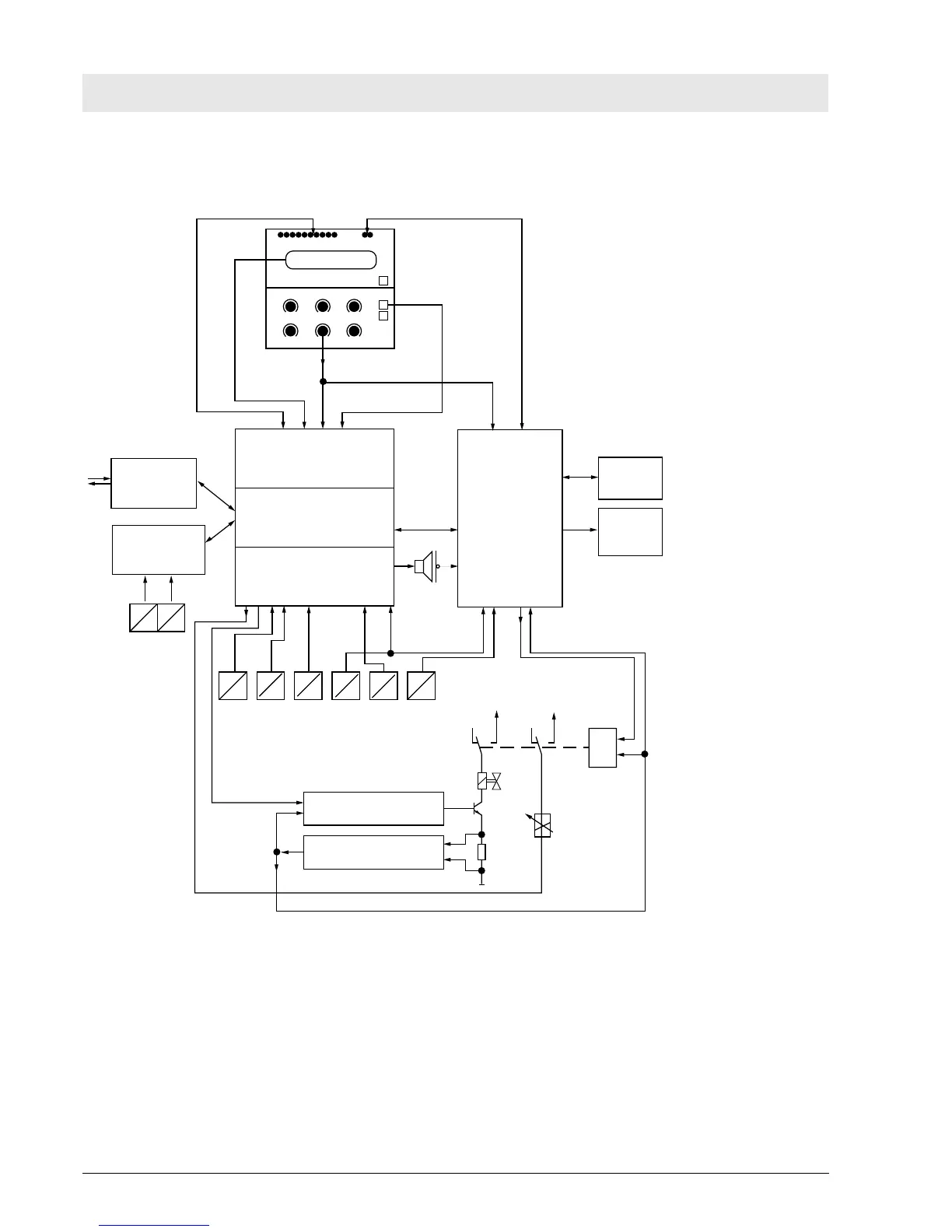
2.3 Block Diagram of the Babylog 8000/ Babylog 8000 plus/Babylog 8000 SC
Fig. 3: Block Diagram of the Babylog 8000/Babylog 8000 plus/Babylog 8000 SC
LEDs 2 red Alarm LEDs
Potentiometer
Front
CPU (Master)
I/O
Communication
Flow
Babylog 8000
Babylog 8000 plus
E
V
E
V
E
P
E
P
E
P
E
P
E
O
E
O
Monitoring
Battery
Reserve
horn
LC display
EL display (Babylog 8000/
Babylog 8000 plus)
keys
Flow sensor
P
AIR
PO2
O2-SensorPexsp
Pinsp
+27 V
+5 V
&
24 Ventile
Valve amplifier
Valve monitoring
PEEP/PIP valve

 Loading...