Dräger Medical AG & Co. KGaA 6173.3
All rights reserved. Copyright reserved.
_ _Printed on_18.05.05_F61733XXT01.fm
51
Function description Babylog 8000
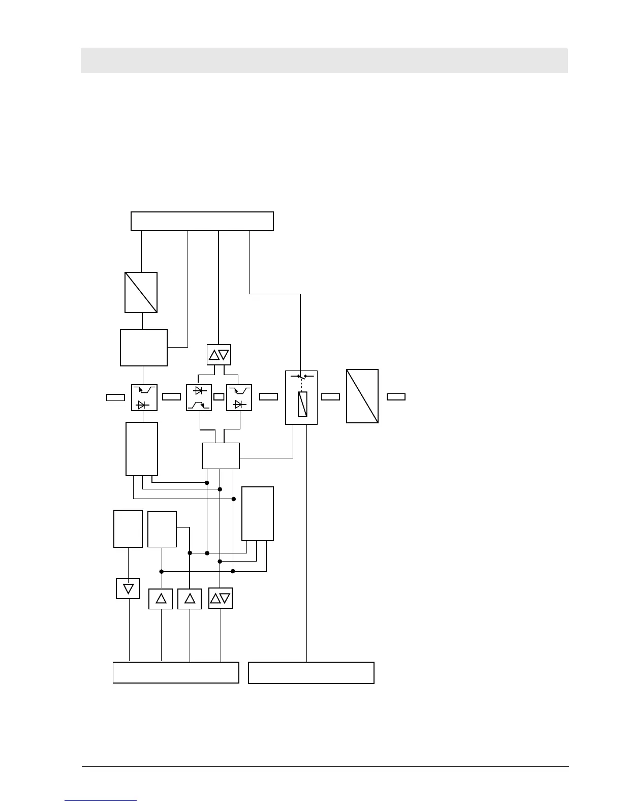
10.14 Communication PCB
The Communication PCB controls an external printer, a computer, and an analog recorder. The
Communication PCB is equipped with an RS232 interface, two 12-bit D/A outputs, and one digital trigger
output. All outputs are electrically isolated from the electronics. Software version 3.00 or higher, a CPU
PCB with 16 MHz (the CPU PCB with 8 MHz was standard until end of 1992) and the Interface PCB with
outputs on the rear panel are minimum requirements for operation.
Fig. 26: Block diagram of the Communication PCB
System connector
Digital bus 68000
I/O connections
DTACK
Control bus
Adress bus
Data bus
DC
DC
EEPROM
MFP*
DTACK
generator
Adress
decoder
2,5 kV electrical isolation
Parallel/seriell
converter
Register
D
A
Analog
Output
Trigger
RS 232
Nurse call
*MFP=Multi Function Prozessor

 Loading...