5664.500/800 Evita 4/Evita 2 dura 06/98 Repair Instructions Page 8
For internal use only. Copyright reserved.
GBR5664500T055664800.fm 18.03.99
Dräger Medizintechnik
D
1.1.2 Voltage Measurement
Important: With devices manufactured end of 96 or later, the extension box connector is no
longer available. The voltages must therefore be measured on the Pneumatics Controller
PCB at pins X3, X11, and X21.
The voltages +5 V and +24 V are connected to digital ground (pin 4). The voltages +15 V,
–15 V, and +12 V are connected to analog ground (Pin 3).
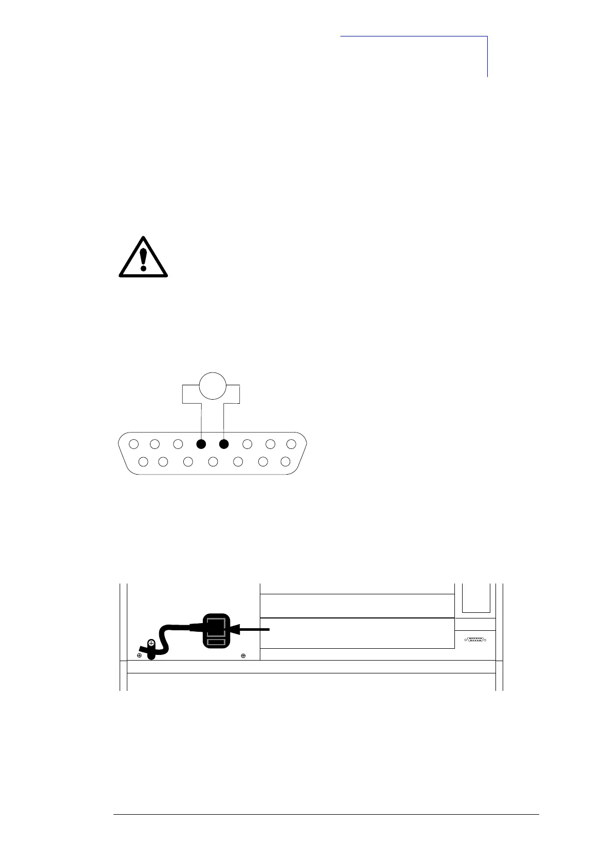
Example of a voltage measurement:
Fig. 2: Sub D socket
• If no voltages are present, check the mains fuses on the rear panel (if the +24 V voltage
is not present, check the control unit for short circuit).
Fig. 3: Rear view (mains fuses)
IMPORTANT
The +5 V voltage is only stable under load. At no-load, the voltage is affected
by interfering pulses. These interfering pulses may cause voltage peaks in the
measured value display. Measure the +5 V voltage only under load.
1
8
9
15
V
+
–
Extensionbox

 Loading...