PAS
®
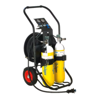
AirPack
Pneumatic Assembly
Instructions for Use
PAS
®
is a registered trademark of Dräger 3357744 (A3-D-P) Page 2 of 3
3.4.2 Connecting air cylinders
Only connect fully charged cylinders that are approved for use, fully
serviceable and in date. Use 200 bar or 300 bar, steel or composite,
breathing air cylinders with compatible connectors (see Section 8). When
more than one cylinder is used, cylinders must be matched for pressure –
do not mix 200 bar and 300 bar cylinders.
1. Ensure that the air cylinder(s) are securely held.
2. Check the outlet port of the air cylinder, and ensure that the O-ring
(Fig 4, Item 1) and the sintered filter (Fig 4, Item 2) in the input
connector are clean and undamaged.
3. Align the input connector (Fig 1, Item 7) with the cylinder ensuring a
smooth curve of the high-pressure hose. Tighten the hand wheel hand
tight. Do not use tools or over tighten.
4. Close the bleed valve (Fig 4, Item 3) (turn it fully clockwise).
3.4.3 Disconnecting air cylinders
WARNING
High-pressure air release may cause injury to the user or other
personnel near the breathing apparatus. Close the cylinder valve
and fully vent the system before attempting to disconnect an air
cylinder.
1. Close the cylinder valve and then open the bleed valve.
2. Disconnect the high-pressure input connector from the cylinder valve.
3.4.4 Connecting an external supply
CAUTION
The cylinder valves must remain fully closed during external-
supply use. If cylinder valves are open, air from the cylinders will
be used.
A compatible external air supply is a regulated medium-pressure input of
breathing air (see Section 8 and Section 10).
1. Select a suitable air supply and adaptor hose.
2. Check that the supply outlet, adaptor hose, and input connector are
clean and undamaged.
3. Connect the external supply to the medium-pressure input connector
of the Pneumatic Assembly (Fig 5).
4. Check that the pressure indicated on the medium-pressure gauge (Fig
1, Item 2) is 6 bar to 10 bar. If necessary, adjust the pressure-
regulating device of the external supply (the nominal setting is 8 bar).
(If the pressure is below 8 bar, a low whistle or hiss may be heard from
the high-pressure whistle during use. This is normal operation for the
unit, and does not affect the functionality of the product).
3.4.5 Functional testing
WARNING
If the breathing equipment fails to meet any of the standards or
parameters described in the functional tests, or if an immediate
leak is evident, there is a system fault. Report the fault to trained
service personnel or contact Dräger. Do not use the breathing
equipment until the fault condition is rectified.
1. Ensure that the cylinder valves and bleed valves are fully closed.
2. Fully open the cylinder valve (open only one cylinder valve on a two
cylinder version).
3. Check the pressures indicated on the pressure gauges:
○ The high-pressure gauge must indicate at least 80% of the cylinder
maximum pressure.
○ The medium-pressure gauge must indicate 6 bar to 10 bar.
4. For two-cylinder versions, fully open the bleed valve of the second/
offline cylinder. Ensure that there is no audible leak and then re-close
the bleed valve.
5. Fully close the online cylinder valve.
6. Wait one minute and then observe the high-pressure gauge and
reopen the cylinder valve. The gauge must not show an increase in
pressure of more than 10 bar. If there is any leak, investigate and
repair the leak before use (see Section 4). If necessary, use a soapy
solution to locate the leak.
7. Fully close the online cylinder valve again.
8. Pull the handle of the relief valve (Fig 1, Item 5) to vent the air very
slowly and observe the high-pressure gauge. The high-pressure
whistle must commence in the range 60 bar to 50 bar.
9. Release the handle of the relief valve immediately when the whistle
commences. Allow the whistle to fully vent the high-pressure side of
the reducer.
10. Again pull the handle of the relief valve to vent the air very slowly and
observe the medium-pressure gauge. The medium-pressure whistle
must commence in the range 5 bar to 4 bar.
Continue testing for two-cylinder versions only.
11. Repeat Steps 2 to 7 for the opposite cylinder.
12. Pull the handle of the relief valve to fully vent the system.
4 Troubleshooting
Disconnect or replace any associated equipment and retest before
referring to the troubleshooting table.
Contact service personnel or Dräger when the remedy information
indicates a service task, or if the symptom remains after all remedy actions
have been attempted.
Symptom Fault Remedy
High-pressure or
medium-pressure air
leak
Loose/damaged
connector or faulty seal
Reconnect or tighten
connectors and retest.
Pressure reducer or
hose leak
Service task
High or low medium-
pressure
Pressure reducer out of
specification
Service task
Poor sounding
whistle
Dirt Clean and retest
Whistle not
functioning correctly
Defective activation
mechanism
Service task
!
!
5 Maintenance
5.1 Maintenance table
Service and test the PAS AirPack Pneumatic Assembly, including out-of-
use equipment, in accordance with this table. Record all servicing and
testing details in the equipment log book. See also the maintenance
information for any associated breathing equipment.
Additional inspection and testing may be required in the country of use to
ensure compliance with national regulations.
Notes
Dräger Recommendations
1. Clean the equipment if it is dirty. If it the equipment has been exposed
to contaminants, disinfect any components that come into direct and
prolonged contact with the skin.
2. These maintenance tasks may only be carried out by Dräger or trained
service personnel. Details of the tests are contained in the technical
manual which is issued to service personnel that have attended a relevant
Dräger maintenance course.
5.2 Air cylinder charging
WARNING
Air quality for compressed-air cylinders must conform to
requirements of EN 12021.
● Refer also to the instructions supplied with the cylinder and the
charging unit for recharging the cylinder.
● Only charge compressed-air cylinders which:
○ Conform to national standards.
○ Feature the original manufacturer’s test date and test mark.
○ Have not exceeded the test date indicated on the cylinder by the
last testing station.
○ Are not damaged.
● To prevent ingress of moisture into the cylinder, ensure that the
cylinder valve remains closed until connected to the charging unit.
● Recharge to the rated working pressure of the cylinder. Dräger
recommend a charge rate of 27 bar/minute (rapid charging will
increase the temperature resulting in an incomplete charge).
● To prevent overcharging of the cylinder, Dräger recommend using a
pressure-limiting device on the charging compressor.
5.3 Cleaning and disinfecting
CAUTION
Do not immerse the PAS AirPack Pneumatic Assembly in water or
cleaning solutions and do not place the PAS AirPack Pneumatic
Assembly in a heated drying facility.
For information about suitable cleaning and disinfecting agents
and their specifications refer to document 9100081 on
www.draeger.com/IFU.
Refer also to the Instructions for Use for the lung demand valve, face mask
and other associated equipment.
● Use only clean lint-free cloths
1. Clean the PAS Airpack Pneumatic Assembly manually using a cloth
moistened with cleaning solution to remove excess dirt.
2. Apply disinfecting solution to all internal and external surfaces.
3. Rinse all components thoroughly with clean water to remove all
cleaning and disinfecting agents.
4. Dry all components using a dry cloth, or in air.
5. Contact service personnel or Dräger if disassembly of pneumatic or
electronic components is required.
6 Storage
Store the equipment between -15 °C and +25 °C. Ensure that the
environment is dry, free from dust and dirt, and does not subject the
equipment to wear or damage due to abrasion. Do not store the equipment
in direct sunlight.
7 Disposal
When required, dispose of the Pneumatic Assembly in line with local or
national regulations for waste disposal.
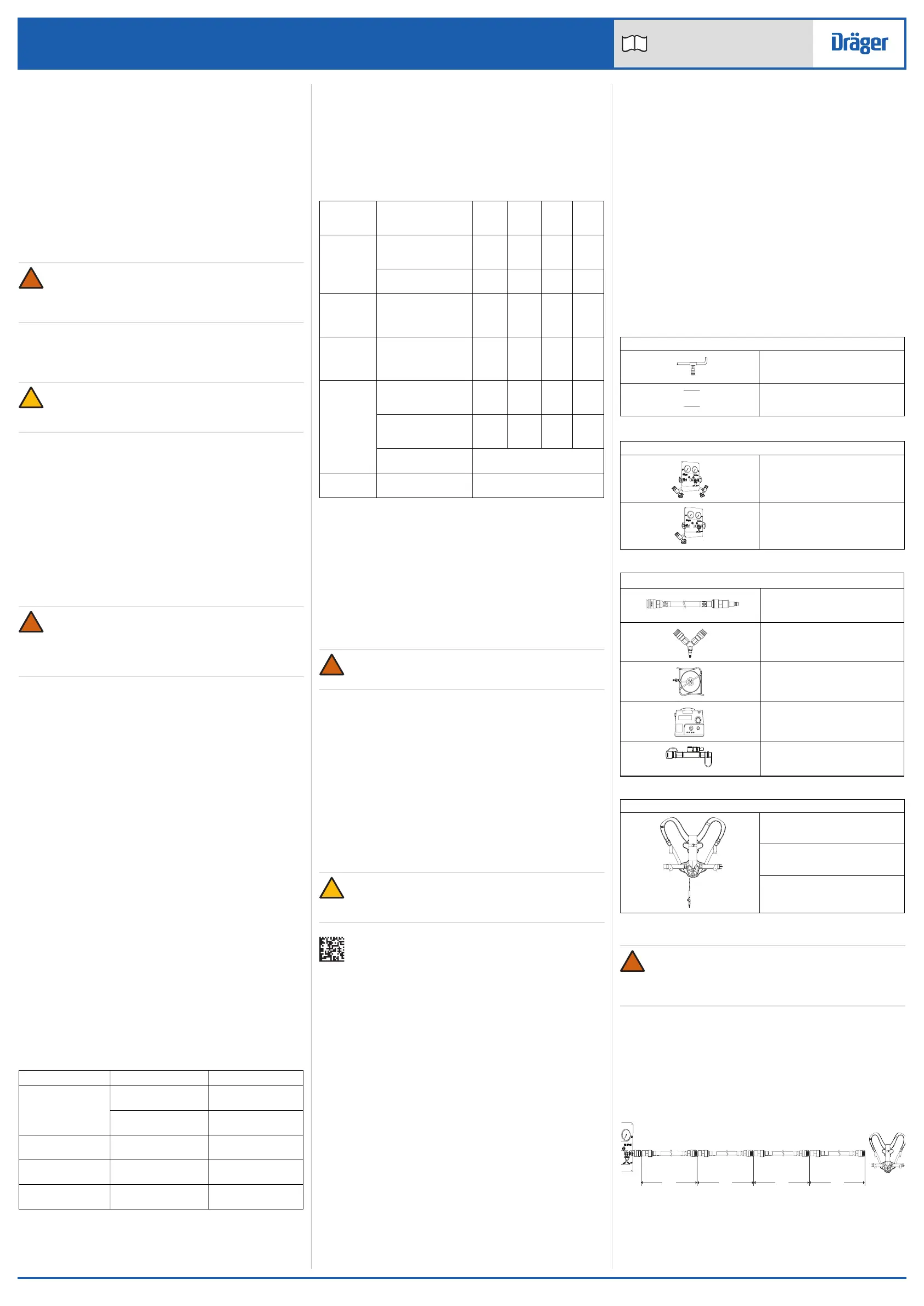
Component/
System
Task After
use
Every
month
Every
year
Every
six
years
Complete
equipment
Visual inspection (see
Note 1 and
Section 3.4.1)
Functional test (see
Section 3.4.5)
High-
pressure
input
connectors
Renew the O-ring and
sintered filter (see
Note 2)
Pressure
reducer
Overhaul. Contact
Dräger for the Repair
Exchange (REX)
service
Cylinder Charge to correct
pressure (see
Section 5.2)
Check the initial test
date stamped on the
cylinder
Cylinder pressure test
and recertification
Carry out in line with national
regulations
Cylinder
valve
Basic overhaul During cylinder pressure test or
on condition
!
8 Technical data
Operating conditions
● Temperature: -30 to +60 °C.
● Usage area: suitable for indoor and outdoor use.
High pressure
● Input connector: 200 bar or 300 bar, standard G5/8” connector as per
EN 144-2.
● Input: 200 bar or 300 bar breathing air cylinder.
Medium pressure
● Input and output connectors: Dräger quick connectors (compatible
with CEJN 344 and Rectus 95KS series).
● Input and output: 6 bar to 10 bar (8 bar nominal) breathing air at a flow
rate of >600 litres/min. Important note: do not exceed 10 bar.
Whistle operation
● High-pressure whistle commences in the range: 60 bar to 50 bar.
● Medium-pressure whistle commences in the range: 5 bar to 4 bar.
● Whistles cease in the range: 1.75 bar to 0 bar.
● Whistle volume: >90 dBA.
9 Compatible airline equipment and
configurations
9.1 Airline equipment configurations
WARNING
Airline equipment must allow the input pressure and flow specified
in the breathing apparatus instructions to be met. Incorrect
configurations may result in insufficient air flow to breathing
apparatus wearers or increase the possibility of air supply failure.
9.1.1 Dräger airline equipment and breathing apparatus
No more than five connections are permitted per line on the output side of
the PAS AirPack Pneumatic Assembly (a Y-piece is treated as two
connections). Additionally, the maximum combined length of the extension
hoses is 100 m. The figures below (not to scale) show some examples of
the maximum number of connections (C1 to C5) and maximum hose
lengths that are permissible in an output configuration using Dräger
equipment.
One breathing apparatus wearer
Breathing air supply equipment
External medium-pressure supply
(see Section 8 for the specification
and connector type)
High-pressure supply (see Section 8
for the specification and connector
type)
Dräger supply, control and monitoring equipment
Dräger PAS AirPack Pneumatic
Assembly (two-cylinder version)
Dräger PAS AirPack Pneumatic
Assembly (one-cylinder version)
Airline equipment (approved to the relevant EN standard)
Extension hose (lengths ranging
from 3 m to 50 m available from
Dräger)
Y-piece
Hose reel (Dräger hose reel has
50 m of hose)
Airline filter unit
In-line medium-pressure whistle
Breathing apparatus
Airline set (EN 14593-1)
Escape/airline set with automatic
switch-over valve (ASV) and airline
connector (EN 402/EN 14593-1)
Working set with automatic switch-
over valve (ASV) and airline
connector (EN 137/EN 14593-1)
45 m
C1
C2
C3
C4
C5
45 m
5 m 5 m
 Loading...