3719543 (A3-D-P) 2 / 8
PSS
®
AirBoss Connect
Self-contained breathing apparatus
Instructions for use
Signals and alarms activate when the remaining pressure in the cylinder
reaches the following levels:
This table shows the default settings for this product. The pressure
limits and display indications for these signals can be configured using
Dräger PC Link (see section 3.1.8.1).
3.1.3.4 Time
The Connect ECU UI module displays elapsed or remaining time
depending on the selected settings. Elapsed time counts and displays the
time since the system was switched on. Remaining time is the time until
low-pressure alarm 1 activates.
Remaining time
Remaining time is the calculated time in minutes until low-pressure alarm 1
activates. The system uses the cylinder pressure and the current
consumption rate of the wearer to calculate and display the time. An initial
calculation is made using a default consumption rate of 50 L/min. The
calculation is then updated once per second using the actual consumption
rate of the wearer (a minimum consumption rate of 50 L/min is applied to
the calculation).
Retreat alert (turn-around retreat alert)
Retreat Alert is an alternative remaining time protocol that can be used if it
is applicable in the country of use (see section 4.2.4.3).
3.1.3.5 Temperature
The Connect ECU UI module contains a thermal sensor which measures
the ambient temperature. The thermal sensor is used to display
temperature on screen and to activate thermal exposure alarms.
The Connect ECU tracks thermal exposure once the temperature is above
a set start temperature (the default start temperature is 40 °C). Two
thermal alarms are activated when the exposure exceed each alarms
threshold. The alarms warn the user of a relatively long period of exposure
to slightly elevated temperatures, or of a short period of exposure in high
temperature situations.
The thermal exposure alarms can be disabled, or the start temperature can
be configured to meet the individual operational needs of the user using
Dräger PC Link (see section 3.1.8.1).
3.1.3.6 DSU
The DSU provides manual and automatic distress alarms. The manual
distress alarm is activated by pressing the manual alarm button to call for
help or attention. The automatic distress alarm uses a motion sensor and
timer to measure the time that the wearer has been motionless (moving
less than normal breathing movement). The DSU uses this information to
activate a pre-alarm and a full alarm at predetermined intervals to indicate
that the wearer could be unconscious or trapped. The automatic distress
alarm activation times are in section 10. The alarm patterns are in
section 4.2.1.2.
A limitation of the automatic distress alarm is that the motion sensor
detects movement or vibration to which the wearer is subjected. If the
wearer is motionless but on a moving platform (on moving or vibrating
machinery for example) the automatic distress alarm might not activate.
3.1.3.7 Buddy-beacon
The buddy-beacon signal helps to see or locate other breathing apparatus
wearers in poorly lit or smoke-filled areas. The normal signal is the blue
LEDs on the Connect ECU UI module and on the rear of the breathing
apparatus pulsing every 3 seconds. The signal changes to the red LEDs
flashing twice per second when low-pressure alarms are activating. If
configured, the signal changes to the amber LEDs pulsing every 3 seconds
when pressure warning 1 is active, and to the red LEDs pulsing every 3
seconds when pressure warning 2 is active.
3.1.3.8 Datalog
The datalog is a record of the event history which is automatically recorded
in the system memory. The datalog stores approximately 200 hours of the
most recent system events. The datalog can be downloaded and viewed
using Dräger PC Link.
3.1.3.9 Card reading system
The Connect ECU UI module has a reader which can upload information
from programmable cards to the system memory. User ID cards store
information about the wearer (e.g. user name, brigade name, and station
number). When the card is read, the system records the user ID in the
datalog.
3.1.4 Compressed air cylinders
The breathing apparatus is compatible with steel or composite material
cylinders of 4 to 9 litre capacities, and 200 or 300 bar pressure. Full
descriptions and user instructions are contained in separate instructions
supplied with the cylinder.
Cylinder
pressure
Signal Pressure display
150 bar Low-pressure warning 1 Amber pulse
100 bar Low-pressure warning 2 Red pulse
55 bar Low-pressure alarm 1 Red flash
10 bar Low pressure alarm 2 Red flash
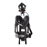
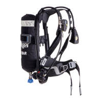
3.1.5 Twin pack
The breathing apparatus may be configured to be fitted with a Dräger twin
pack (Fig 4).
The twin pack holds two compressed-air cylinders secured on to a
mounting bracket by a pair of straps. The mounting bracket fits into the
reducer mount on the backplate and is secured by locating pins at the
cylinder cradle.
The twin pack holds two 6 litre or 6.8 litre capacity 300 bar cylinders. One
of the cylinders is fitted with a cylinder valve and the other cylinder has a
high-pressure adaptor. A stainless steel capillary tube between the
cylinder valve and the high-pressure adaptor makes a pneumatic
connection between the two cylinders. The connecting arrangement is
protected inside a split plastic cover which can also be used as a carrying
handle.
The cylinder valve used on the twin pack is a screw-type which is
positioned on the inside of the cylinders (toward the backplate) when the
twin pack is connected to the breathing apparatus.
The twin pack can only be fitted or removed by Dräger or trained service
personnel. Details of the procedures are contained in the technical manual
which is issued to service personnel that have attended a relevant Dräger
maintenance course.
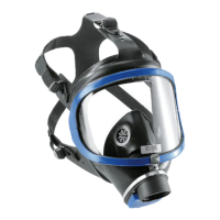
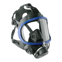
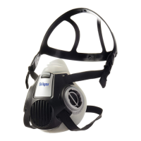
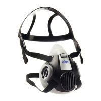
3.1.6 Face masks
The breathing apparatus is compatible with FPS
®
7000 and Panorama
®
Nova face masks. Full descriptions and user instructions are contained in
separate instructions supplied with the face mask.
3.1.7 Lung demand valves
The breathing apparatus is compatible with PSS
®
lung demand valves with
the following types of connector: A, AE, ESA, and N. Full descriptions and
user instructions are contained in separate instructions supplied with the
lung demand valve.
3.1.8 Optional features and equipment
3.1.8.1 PC Link
PC Link is a software application that uses RF and Bluetooth
®
dongles to
read and configure Dräger electronic monitoring systems. Configurable
settings and parameters include alarm patterns, warning levels, timings,
and start-up options. Readable information includes the product
identification details, the firmware versions, and the datalog.
PC Link can also read and write information on programmable cards which
are available from Dräger for use with this product (see section 3.1.3.9).
See the PC Link instructions for use or contact Dräger for more
information.
The settings specified in these instructions for use (pressures, alarm
patterns, start-up options, etc.) are the default configuration settings
for this product.)
3.1.8.2 Telemetry
The Connect ECU is compatible with Dräger telemetry systems, such as
the Dräger PSS
®
Merlin
®
. The telemetry system is used to monitor and
control breathing apparatus wearers that are deployed at an incident. The
telemetry system uses radio communication to transmit status and
information signals between deployed breathing apparatus wearers and
an external entry control board or software system.
3.2 Intended use
When the product is used with an approved compressed air cylinder, mask
and lung demand valve, the breathing apparatus provides a wearer with
respiratory protection for working in contaminated or oxygen-deficient
conditions.
The electronic monitoring system provides accurate cylinder pressure,
time, and temperature information, and activates alarm signals at critical
points. The integrated DSU provides clear, distinct, and easily recognized
alarm signals that indicate wearer immobilization or a call for help or
attention.
The compressed air cylinder, mask, lung demand valve, and other
accessories used with this product must be certified Dräger components.
They must be assembled in an approved configuration and used as
described in this document and in separate instructions supplied with the
accessories, otherwise operation of the product may be impaired.
3.3 Use in explosive atmospheres
The PSS AirBoss Connect, as defined in the feature description
(section 3.1), is type tested for use in potentially explosive atmospheres
and is suitable for use in hazardous areas up to and including zone 0 and
zone 20. For further information please contact Dräger.
4
5506
3.4 Limitations on use
All electronic devices could suffer a temporary loss of function if subjected
to high levels of RF radiation. The system operates with no loss of
performance or function when the RF radiation is removed.
3.5 Approvals
The European standards, guidelines, and directives according to which
this product is approved are specified in the declaration of conformity (see
the declaration of conformity or www.draeger.com/product-certificates).
Electronic sub-assemblies are suitable for use in the following zones:
I M1 Ex ia I Ma
II 1G Ex ia IIC t4 Ga
II 1D Ex ia IIIB T135 °C Da
Ta −30 °C to +60 °C
3.6 Product marking and symbols
3.6.1 Product marking
Do not remove or alter any product label or marking.
Labels (Fig 5) on the product provide the following information:
The following symbols can also be found on the product.
Refer to the relevant authority for explanation of approval body symbols
and marking on the product.
3.6.2 LCD screen symbols
EU approvals
CE 2575 CE marking and identification number of notified body
ITS-I 21 ATEX 29986 ATEX approval certificate reference
IEC approvals
IECEx ITS 21.0025 IECEx approval certificate reference
UK approvals
UKCA 0359 UKCA marking and identification number of approval body
ITS 21 UKEX 0328 UKEX approval certificate reference
No Description
1 Dräger part number
2 Approval information (see section 3.5)
3 Address of manufacturer
4 Attention! Read and comply with the instructions for use.
5 Product disposal (see section 9)
6 Manufacturer
7 Component name
8 Operating frequency
9 Product name
10 Dräger part number
11 Dräger serial number
12 Approval information (see section 3.5)
13 Year of manufacture
14 Manufacturer
15 Label part number
Symbol Description
Radio-frequency identification symbol
Note for disposal
Caution! Follow the instructions for use.
General symbols
Passed or complete Open cylinder valve
Failed or cancelled Close cylinder valve
Switch off/on Cylinder pressure too low
Retry or refresh Leak test fail
Cancel Leak test pass
Battery good – Full Leak test error
Battery good – 3/4 Leak test timing
5
0098/
Made by Draeger Safety UK Limited
Only MED Compliant
when fitted with a
Dr
ae
ger Approved
Safety Line
PART No:
PSS AirBoss
SERIAL No:
3713276
9
10
11
12
13
14 15
5529/5330
1
2
3
4
5
6
8 7
 Loading...