3719543 (A3-D-P) 3 / 8
PSS
®
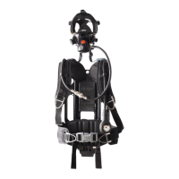
AirBoss Connect
Self-contained breathing apparatus
Instructions for use
4 Use
WARNING
Only trained and competent users (those who have attended a relevant
training course) are permitted to prepare and use this product.
► Ensure that any accessories, ancillary equipment, and other
protective clothing items do not interfere with the breathing apparatus
and do not create a safety hazard.
WARNING
The effective working duration of the breathing apparatus depends on the
initial air supply available and the breathing rate of the wearer.
► Fill compressed air cylinders to their full rated pressure before use.
► Do not commence any operation using a cylinder that is less than 90
percent full.
CAUTION
Equipment damage can cause the release of high-pressure air.
► Do not apply excessive force or use tools to open or close a cylinder
valve.
► Do not drop or throw down the breathing apparatus.
4.1 Preparation for use
4.1.1 First use of the breathing apparatus
On receipt of the product, the LCD screen and LED panel have thin flexible
film covers for protection. Remove the film covers before the first
use (Fig 6).
The LCD screen and LED panel also have external protective covers.
Do not remove the protective covers.
4.1.2 Before using the breathing apparatus
1. Carry out a visual inspection of the breathing apparatus (see
section 6.3.1).
2. If using a breathing apparatus with universal accessory clips, ensure
that blanking plugs are fitted to all clips that are not fitted with
accessories.
3. Fit the batteries if necessary (see section 4.5.6).
4. Fit the cylinder (see section 4.5.7).
5. If using a breathing apparatus with an adjustable backplate, adjust the
height to the position required by the wearer (see section 4.5.3).
6. Check the male element of the medium-pressure quick coupling for
burring (see section 6.3.2).
7. If using a push-in type lung demand valve, check the connector for
lubricant (see section 4.5.4).
8. If using a positive pressure lung demand valve, press the reset button
(Fig 7, Item 1) to switch off the positive pressure.
9. Carry out a full functional test of the breathing apparatus (see
section 6.3.4).
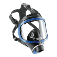
10. Connect the lung demand valve to the mask (see the lung demand
valve instructions for use). Check the security of attachment by gently
attempting to pull the coupling apart.
11. Put on the breathing apparatus (see section 4.5.1).
4.2 Using Connect ECU
4.2.1 Operating concept
4.2.1.1 System controls
The following controls activate product functionality.
– Press = Press and release the button.
– Hold = Press and hold the button for 2 seconds.
Battery good – half Timed out
Battery warning PC Link connection
Battery critical Read card
Manual distress alarm Invalid card content
Automatic distress alarm No card detected
Perform leak test Quiet mode
Telemetry symbols
Active communication Voluntary withdrawal
Lost communication Evacuate
Not logged on
Retreat alert symbols
TTR Arrival point
Retreat
General symbols
sos
6
5210
7
2739
1
2
Each time a button is pressed a single tone sounds, or the alarm volume
is briefly reduced if an alarm is sounding.
4.2.1.2 Alarm patterns
Pre-alarm signal
An increasing-volume 3-tone alarm sounds, and the red and blue LEDs on
the Connect ECU UI module flash.
Full alarm signal
A high-pitched repeating alarm tone sounds.
– During DSU alarms, the red and blue LEDs flash 3 times intermittently.
– displays during automatic distress alarms.
– displays during manual distress alarms.
– During thermal exposure alarm 2, the red LEDs flash twice per second.
– During system fault alarms, the red LEDs flash once per second.
Low-pressure alarm 1
An intermittent high-pitched alarm sounds, the red LEDs pulse every 3
seconds, and the graphical pressure display turns red.
Low-pressure alarm 2
An intermittent high-pitched alarm sounds, the red LEDs flash once, and
the graphical pressure display remains red.
4.2.1.3 Switching on
Normal switch on
Switch on the system using any of the following:
– Install the power pack.
– Hold the left-hand or right-hand button (configuration-dependent).
– Simultaneously hold the both side buttons.
– Remove the key (configuration-dependent).
– Open the cylinder valve to pressurize the pneumatic system.
Self-test
When the system switches on (with or without an air cylinder fitted), the
self-test runs. The system indicates a self-test pass or fail.
– Self-test pass. The system enters the start-up sequence (see
section 4.2.1.5).
– Self-test fail. The Connect ECU UI module displays the fault code, and
the red and blue LEDs flash 3 times intermittently.
– Note the fault code and contact service personnel or Dräger.
– The system automatically switches off after the preset time. To
switch off immediately, press the right-hand button .
System information switch on
Hold the left-hand button to switch on and display system information
including serial numbers, firmware versions, approval information, etc.
– If there is more than one page, press the left-hand button to scroll
through system information.
– Press the right-hand button to return to the normal switch on
sequence.
4.2.1.4 Alarm switch on
If the manual alarm of the DSU activates when the system is off, the
system automatically switches on in alarm mode. The self-test and start-
up sequences are omitted when the system switches on in an alarm mode.
Manual alarm switch on
To switch on the system and immediately activate the manual distress
alarm, press the manual alarm button.
4.2.1.5 Start-up
When the self-test completes successfully the Connect ECU UI module
displays the start-up menu. The contents of the menu can be configured
individually for different switch-on methods.
Control Action Function
Left-hand button Press Selects the choice indicated on screen
Activates the LCD screen if deactivated
Cycles through available operational information
(remaining time, temperature, etc.)
Hold
Switches on the system if switched off
1
1. If configured
Displays a menu if menu options are available
Right-hand button Press Selects the choice indicated on screen
Activates the LCD screen if deactivated
Cycles through available operational information
(remaining time, temperature, etc.)
Acknowledges an evacuation request during
telemetry operations
Hold
Switches on the system if switched off
1
Sends a voluntary withdrawal
2
request during
telemetry operations
2. Voluntary withdrawal is referred to as early retreat during Retreat Alert
operations.
Both buttons Hold
Switches on the system if switched off
1
Switches off the system if switched on
1
Silences or cancels alarms
1
Manual alarm button Hold Activates the manual distress alarm (including
when the system is switched off)
Key Remove
Switches on the system if switched off
1
Insert
Switches off the system if switched on
1
Silences or cancels alarms
1
Cylinder valve Open Switches on the system if switched off
Connect ECU UI
module
Move Cancels the DSU pre-alarm when activated
Programmable card Read Uploads card data to the system memory
Some start-up menu content is mandatory when the device is switched
on by installing the power pack.
When all applicable menu options have been displayed the device enters
operational mode (see section 4.3.1).
– Press the left-hand button or right-hand button to accept or
acknowledge the on-screen message and progress to the next stage
immediately.
– If failure conditions are detected, the system switches off. Failure
conditions include critical battery level, system time-out, leak detected,
and system errors.
If the system switches off and is still pressurized, it could immediately
switch on and restart the start-up sequence.
Start-up sequence
– If the system is switched on by installing the power pack, the system
will detect which power pack has been installed.
– If a primary power pack has been installed, the user is prompted
to confirm whether the batteries have been replaced.
– If the user confirms that the batteries have been replaced, the user
will be prompted to confirm the battery type (alkaline or lithium).
– Battery level (see section 4.2.2).
– Cylinder selection (see section 4.2.3).
– PC Link. Select to enable wireless connection to PC Link (see
section 3.1.8.1).
– High-pressure leak test (see section 6.3.4.2).
– Read card (see section 4.2.4.1).
– Quiet mode (see section 4.2.4.2).
4.2.2 Battery level
The battery level is indicated as follows:
– Battery good (Fig 8). The battery charge is sufficient to remain above
the critical level during the current operation.
– Select to proceed.
– Battery warning (Fig 9). The battery charge could reach the critical
level during the maximum operating time available for the breathing
apparatus configuration.
– Select to proceed, or select to switch off.
– Replace the batteries before the next operational use.
– Battery critical (Fig 10). The battery charge is not sufficient to support
an operational use.
– Select to switch off.
– Replace the batteries.
4.2.3 Cylinder selection
The Cylinder Selection screen shows the currently selected cylinder.
– Press the right-hand button to confirm the currently selected cylinders
and proceed to the next sub-menu (if any are configured).
8
5202
9
5203
10
5204
Confirm cylinder
6.8 L
300 bar
11
5531
 Loading...