3719543 (A3-D-P) 5 / 8
PSS
®
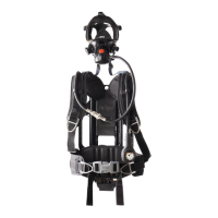
AirBoss Connect
Self-contained breathing apparatus
Instructions for use
Button configuration
– Hold the right-hand and left-hand buttons until the display clears, then
immediately release the buttons. If the key was removed, refit the key.
4.4.2 After using the breathing apparatus
1. Take off the breathing apparatus (see section 4.5.2).
2. Carry out a visual inspection of the breathing apparatus (see
section 6.3.1).
3. Carry out a full functional test of the breathing apparatus (see
section 6.3.4).
4. If using a push-in type lung demand valve, check the connector for
lubricant (see section 4.5.4).
5. Remove the cylinder if necessary (see section 4.5.7).
6. Charge the cylinder (see section 6.3.5).
7. Pass the breathing apparatus to the service department with details of
any faults or damage that occurred during use.
4.5 Common tasks
4.5.1 Putting on the breathing apparatus
1. Fully loosen the shoulder straps and waist belt.
2. Put on the breathing apparatus.
3. Check that the shoulder pads are not twisted then take the weight of
the breathing apparatus on the shoulders by pulling the shoulder pull-
down straps. Do not fully tighten at this stage.
4. Close the waist belt buckle.
5. Pull the ends of the waist belt forward until the belt padding fits
securely and comfortably over the hips (Fig 17).
6. Tuck the belt straps behind the waist pad.
7. Pull the shoulder pull-down straps until the breathing apparatus rests
securely and comfortably on the hips. Do not over tighten.
8. Pull the strap retainers down to secure the strap ends (Fig 18).
9. Fully loosen the mask straps.
10. Place the neck strap over the back of the neck (Fig 19).
11. Press the reset button (Fig 7, Item 1).
12. Open the cylinder valve slowly, but fully, to pressurize the system.
13. Carry out the start-up condition checks (see section 4.2.1.5) and leak
tests (see section 6.3.4). Carry out other start-up functions as required.
– On completion of the start-up sequence, the system enters active
mode.
Dräger recommend that the cylinder should be full at the start of any
operation or sequence of operations. The cylinder pressure must be at
least 165 bar to carry out the high-pressure leak test.
14. Check the cylinder pressure reading to ensure that there is sufficient
air in the cylinder for the operation.
15. Carry out a functional test of the electronic system (see section 6.3.4).
16. Set the DSU automatic distress alarm for operation as follows.
– Key configuration. Remove the key to activate the motion sensor.
– Button configuration. Remove the key if the motion sensor is
required.
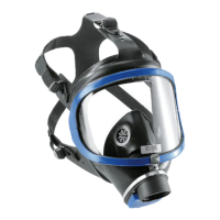
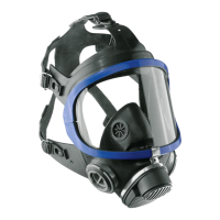
17. Put on the mask and check the seal between the mask and the face of
the wearer (see the mask instructions for use).
4.5.2 Taking off the breathing apparatus
WARNING
Removing the breathing apparatus in a hazardous breathing environment
is unsafe.
► Do not remove the breathing apparatus until in a safe breathing
environment.
NOTICE
The product can be damaged if removed incorrectly.
► Do not remove the mask by pulling the lung demand valve.
1. Loosen the mask straps.
2. At the point when the seal between the mask and face is broken, press
the reset button (Fig 7, Item 1).
3. Fully remove the mask and extend all the straps.
4. Close the cylinder valve.
5. Press the front button (Fig 7, Item 2) to vent the pneumatic system.
6. Press the reset button (Fig 7, Item 1).
7. Release the waist belt buckle.
17
5283
18
5284
19
5292
8. Lift the shoulder harness ends to release the strap retainers (Fig 20)
and then lift the shoulder strap buckles to loosen the straps.
9. Take off the breathing apparatus.
4.5.3 Adjusting the backplate height
1. Lift the apparatus into the vertical position.
2. Simultaneously press the two spring-loaded buttons (Fig 21).
3. Slide the yoke in the required direction then release the buttons.
4. Continue sliding the yoke until the buttons engage and lock the yoke in
the required position.
4.5.4 Checking and re-lubricating the lung demand valve coupling
This task applies only to the following lung demand valve types: A and
ESA.
As a guide, lubricant should be felt on the fingers but not seen. If
relubrication is required, lightly apply Molykote
®
111 (other lubricants are
not tested and may damage the equipment).
– For type A check for lubricant on the O-ring of the lung demand valve
connector.
– For type ESA check the outer surface of the male part of the push-in
connector on the lung demand valve.
4.5.5 Using universal accessory clips
4.5.5.1 Fitting an accessory to a universal accessory clip
Work equipment
– 2.5 mm hexagon key
1. Remove the blanking plug from the universal accessory clip (see
Fig 22).
2. Slide the compatible accessory into the universal accessory clip (see
Fig 23).
3. Ensure that the accessory is securely retained by the universal
accessory clip.
4.5.5.2 Removing an accessory from a universal accessory clip
Work equipment
– 2.5 mm hexagon key
1. Remove the accessory from the universal accessory clip (see Fig 24).
20
5285
21
5289
22
5293
23
5294
24
5295
2. Slide a blanking plug into the universal accessory clip (see Fig 25) to
protect it.
3. Ensure that the blanking plug is securely retained by the universal
accessory clip.
4.5.6 Fitting or replacing batteries
4.5.6.1 Fitting the power pack
1. Inspect the power pack and electronic monitoring system (see
section 6.3.1), paying particular attention to the battery terminals and
sealing rim.
2. Insert the power pack into the recess in the electronic monitoring
system (Fig 26).
3. Push down firmly to lock the power pack (Fig 27). Ensure that the
2 sliding latches are engaged when viewed through the 2 keyholes
and that the power pack is securely locked in place.
– When the power pack connects, a tone sounds and the start-up
sequence commences (see section 4.2.1.5).
4.5.6.2 Removing the power pack
A removal key (Dräger part number 3356667) is supplied with the
breathing apparatus.
1. Insert and press down the removal key (Fig 28).
2. Remove the power pack.
4.5.6.3 Replacing 1.5 V batteries
WARNING
Improper handling and use of batteries may cause an explosion, a fire, or
a chemical hazard.
► Do not remove or install the batteries in a flammable atmosphere.
► Do not expose the batteries to heat sources.
► Do not attempt to recharge any non-rechargeable battery.
► Do not short out the battery terminals.
► Use only the recommended battery type.
► Replace batteries as a matched set and do not mix new and used
batteries.
NOTICE
Batteries that are not correctly disposed of may cause an environmental
hazard.
► Dispose of used batteries in accordance with national or local
regulations.
Use only the following approved battery types.
– Procell
®
LR6 (1.5 V)
– Varta
®
Industrial Pro LR6 (1.5 V)
– Energizer
®
Ultimate FR6 (1.5 V)
– Ansmann
®
Industrial FR6 (1.5 V)
– Huiderui
®
FR6 (1.5 V)
Work equipment
– 2.5 mm hexagon key
– Torque wrench (1 Nm)
1. Remove the power pack (see section 4.5.6.2).
25
5329
26
5429
27
5430
28
5431
 Loading...