3719543 (A3-D-P) 7 / 8
PSS
®
AirBoss Connect
Self-contained breathing apparatus
Instructions for use
– Above the centre bar of the adjuster buckle (B, twin cylinder strap
configured for use with a single cylinder).
3. Close the cam lever, and check that the cylinder is secure.
4. If the cylinder is not secure, release the cam lever and move the
adjuster buckle to adjust cylinder strap tension.
– Move the adjuster buckle toward the cam lever to loosen the strap.
– Move the adjuster buckle away from the cam lever to tighten the
strap.
5. Continue to test and adjust until the cylinder is secure.
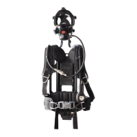
4.5.7.8 Adjusting the twin cylinder strap
1. Fit the cylinders but do not close the cam lever (see section 4.5.7.2).
2. Move the adjuster buckle (Fig 47, Item 1) so that the stitching is below
the centre bar of the adjuster buckle.
3. Close the cam lever, and check that the cylinders are secure.
4. If the cylinders are not secure, release the cam lever and move the
adjuster buckle to adjust cylinder strap tension.
– Move the adjuster buckle toward the cam lever to loosen the strap.
– Move the adjuster buckle away from the cam lever to tighten the
strap.
5. Continue to test and adjust until the cylinders are secure.
5 Troubleshooting
The troubleshooting guide shows fault diagnosis and repair information
applicable to users of this product. Further troubleshooting and repair
information is available in instructions for use supplied with associated
equipment.
Where the troubleshooting guide shows more than one fault or remedy,
carry out repair actions in the order that they appear in the guide.
Contact trained service personnel or Dräger when the remedy information
indicates a service task, or if the symptom remains after all remedy actions
have been attempted.
5.1 Troubleshooting for breathing apparatus
5.2 Troubleshooting for Connect ECU
Symptom Fault Remedy
High-pressure air leak or
failed leak test
Loose or dirty connector Disconnect, clean and
reconnect couplings
and retest
Faulty hose or component Substitute user
replaceable
accessories and retest
Air leak from medium-
pressure hose connector at
the pressure reducer
(pressure relief valve) (see
Fig 2)
Faulty O-ring, retainer,
spring, or pressure reducer
Service task
Air leak from lung demand
valve
Ice particles on sealing
elements
Allow a rush of air to
pass through the valve
by pressing the front
button (Fig 7, Item 2)
then quickly switch off
the positive pressure by
pressing the reset
button (Fig 7, Item 1)
Air leak from cylinder
connector
Ice particles on sealing
elements
Close the cylinder valve
and vent the system.
Disconnect then
reconnect the cylinder.
Pressurize the system
by opening the cylinder
valve slowly, but fully.
Poor sounding whistle Whistle dirty Clean the whistle flute
and retest
Whistle not functioning Activation mechanism fault Service task
Difficulty connecting or
disconnecting the medium-
pressure quick coupling
Dirty connector Disconnect, clean and
reconnect couplings,
and retest
Burring of the male coupling Replace the hose with
the male coupling
Symptom Fault Remedy
Fault indication during the
self-test or when switching
off
See section 5.2.1 Note the fault code and
contact service
personnel or Dräger
A B
46
5305/5469
1
47
5334
1
5.2.1 Fault indication
Faults that are detected by the system are indicated on the screen with a
fault code (see Fig 48). The code is separated into groups to identify the
applicable system and nature of the fault.
If a fault indication displays during the self-test or when switching off, note
the fault code and contact service personnel or Dräger. System faults
which occur during use are described in section 4.3.2.
6 Maintenance
6.1 Maintenance table
Service and test the product, including out-of-use equipment, in
accordance with the maintenance table. Record all service details and
testing. Refer also to the instructions for use for other associated
equipment.
Additional inspection and testing may be required in the country of use to
ensure compliance with national regulations.
High-pressure leak test
fail
Loose or dirty connector Disconnect, clean and
reconnect couplings
and retest
Faulty hose or component Substitute user
replaceable
accessories and retest
Battery warning
Low battery level Replace the batteries
before the next
operation
1
Battery critical
Critical battery level Replace the batteries
before use
1
Fails to switch on Very low battery level
Replace the batteries
1
Poor battery connection Inspect and clean the
battery holder and
terminals (see
section 6.2). Contact
service personnel or
Dräger if there is any
damage
Fails to switch off Pressure reading is not
below the preset value
Close the cylinder valve
and fully vent the
pneumatic system
Key fault Replace the key
Inserting or removing the
key fails to trigger the
expected action (for
example, silencing or
cancelling alarms)
Power pack not inserted
correctly
Remove and refit the
power pack (see
section 4.5.6.1)
LCD screen or LED panel
obscured or illegible
Dirty screen or water/
condensation ingress
Remove and clean the
protective cover (see
section 6.2)
Protective cover marked or
damaged
Replace the screen
System fault or damage Contact service
personnel or Dräger
1. For battery replacement, see section 4.5.6.
Item Task
Every
month
Every
year
Every
10
years
Complete
product
Visual inspection (see section 6.3.1) X
Functional testing (see section 6.3.4) X
Breathing cycle and static tests
1)
1. These maintenance tasks can only be carried out by Dräger or trained
service personnel. Details of the tests are contained in the technical
manual which is issued to service personnel that have attended a
relevant Dräger maintenance course.
X
Lung
demand
valve
Check the male element of the quick
coupling for burring (see section 6.3.2)
X
Pressure
reducer
Inspect the sintered filter
1) 2)
2. Replace the sintered filter if a drop in pressure reducer performance is
observed during a flow check or if it is visibly damaged.
X
Inspect the high-pressure connector O-
ring
1) 3)
3. Replace the high-pressure connector O-ring if it is found to leak during
functional testing or if it is visibly damaged.
X
Overhaul. Contact Dräger for the Repair
Exchange (REX) service
4)
4. Where the breathing apparatus is subjected to a high level of use (in
training establishments etc.), reduce the overhaul period for the
pressure reducer. In these circumstances, Dräger recommend that the
overhaul frequency should be less than 5 000 applications of use. An
application of use is defined as a single use of the fully assembled
breathing apparatus, where the user breathes from the air cylinder. It
does not include system pressurization for pre-operational checks.
X
Cylinder Check test date of cylinder X
Recertification According to national
regulations in the country
of use
Symptom Fault Remedy
48
5306
6.2 Cleaning and disinfecting
CAUTION
Trapped water and ice inside the pneumatic system can impair the
operation of the product.
► Prevent any liquid from entering the pneumatic system, and
thoroughly dry the product after cleaning and disinfecting.
NOTICE
Using cleaning and disinfecting methods not described in this section can
damage the equipment.
► Do not exceed 60 °C for drying, and remove components from the
drying facility immediately when dry. Drying time in a heated dryer
must not exceed 30 minutes.
► Do not immerse pneumatic or electronic components in cleaning and
disinfecting solutions or water.
For information about suitable cleaning and disinfecting agents
and their specifications refer to document 9100081 at
www.draeger.com/IFU.
6.2.1 Cleaning and disinfecting the breathing apparatus
Clean the breathing apparatus if it is dirty. If the equipment has been
exposed to contaminants, disinfect any components that come into direct
and prolonged contact with the skin.
Refer also to the instructions for use for the lung demand valve, mask, and
other associated equipment. Contact service personnel or Dräger if
disassembly of pneumatic or electronic components is required.
Work equipment
– Use only clean lint-free cloths
1. Clean the breathing apparatus manually using a cloth moistened with
cleaning solution to remove excess dirt. Remove and clean the
following:
– The protective covers (see section 6.3.3). Clean the protective
covers and the LCD screen and LED panel.
– The power pack (see section 4.5.6.2). Clean the power pack and
compartment, and ensure that the contacts and locking
mechanism are clean, dry and undamaged.
2. Apply disinfecting solution to all internal and external surfaces.
3. Rinse all components thoroughly with clean water to remove all
cleaning and disinfecting agents.
4. Dry all components using a dry cloth, in a heated dryer, or in air.
5. Carry out a full electronic monitoring system functional test (see
section 6.3.4.1).
6.3 Maintenance tasks
6.3.1 Visual inspection
A visual inspection must fully check the product including all component
parts and accessories.
1. Check that the product is clean and undamaged, paying particular
attention to pneumatic system components, connectors, and
elastomeric components such as hoses.
– Typical signs of damage that can affect the operation of the
product include impact, abrasion, cutting, corrosion, and
discoloration.
2. Report damage to service personnel or Dräger, and do not use the
product until faults are rectified.
6.3.2 Checking the medium-pressure quick coupling
This task applies only to breathing apparatus with a removable lung
demand valve. If there is any difficultly disconnecting or connecting, see
the troubleshooting information in section 5.
1. Press the male element into the female element of the coupling until
an audible click is heard.
2. Disconnect the male element from the female element of the quick
coupling.
3. Reconnect the quick coupling as per step 1.
6.3.3 Replacing the Connect ECU UI module protective covers
NOTICE
Sharp objects can damage the equipment.
► Do not use sharp objects or tools to remove the rubber cover.
1. 1. If the Connect ECU UI module is fitted with a key:
a. Remove the key.
b. Switch off the system (see section 4.4.1).
2. Remove the rubber band from the bottom of the rubber cover and then
slide it down the hose (Fig 49).
3. Fold back the rubber cover (Fig 50).
49
5432
50
5433
 Loading...