11
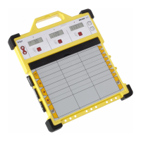
5. Indicating and control elements
Button F1: Select menu
Button F2 Accept value
Reset button Reset horn and alarm
Potentiometer L Adjust values
Power LED (green) Supply voltage present
Hu LED (red) Horn
Error LED (yellow) Fault
LEDs A to F (red) Alarm
x10 LED (green) Multiply displayed value by
10 for actual gas reading
3-pin connector RS232 interface
Press F2 button ➾ Stop display scrolling
F2 button not pressed ➾ display continuously scrolling
The following configuration applies for all measuring channels:
One relay each for common alarm and horn.
One button for resetting the horn and alarms.
Alarm memory is integrated.
LEDs indicate the operating statuses.
117
Power Reset
Channel A B C D E F
Concentration
F1 F2
x10 Error L
A
Hu
BC
DEF
A1
A2
A3
A4
18
35
RailGard-S6
 Loading...