15
Transmitter Concentration
xxx
not activatedTransmitter
FFO
C
C
Axxx
AFFO
Transmitter Concentration
xxx
not activatedTransmitter
FFO
B
B
Transmitter Concentration
not activated
Transmitter
Transmitter Concentration
xxx
not activatedTransmitter
FF
O
Transmitter Concentration
xx x
not activatedTransmitter
FFO
Transmitter Concentration
xxx
not activatedTransmitter
FFO
D
D
E
E
F
F
Main menu
A1
A2
A3
A4
ABCD
EF
Alarm
field
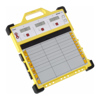
7. Operation
7.1. Signal Outputs
Control Unit
Powering up the Dräger RailGard will start a lamp display
test. Then the display indicates "WAIT".
Further actions are depending on the configuration of the
Dräger RailGard.
Main menu
The sensors are cyclically interrogated and their measured
values are displayed in connection with the sensor
identifiers. The display will indicate “OFF” for deactivated
channels instead of the measuring value(s).
The alarm matrix distinguishes between channels and
relays:
x: channel number A-F
y: Output relay A1
Output relay A2
Output relay A3
Output relay A4
Example: in the event of an alarm conditions on channel A –
a dot is displayed in row A1 and column A
Pressing the F2 button will stop the scrolling display.
 Loading...