DM - Operating Instructions, Installation Instructions, Wiring diagrams Version 3.1.765 August 2019 7
2. Assembly of Unit It is suggested that this is done in a clear space on the
floor.
FAN: Mount fan brackets to side of fan.
HEATER (on heated models): Fit to inlet of fan using 4 screws provided
(note airflow direction for fan is shown by an arrow on the terminal
cover). Ensure airflow direction arrow on heater is the same as
direction on fan, ensure heater is mounted so marked top is installed
upright. Ensure heater is level.
FILTER BOX: Fit to heater (on heated models), or fit to the fan using the
supplied collar, so that the hanging bracket is on the heater/fan inlet
side. Ensure airflow direction arrow on filter is same as fan.
PRE FILTER: Fit white pre filter bag to inlet of filter box.
3. Pre Wiring Using supplied flying leads, connect attic control unit to fan
and heater (on heated models). Check wiring diagrams on components
carefully.
4. Installing in Attic Lift assembled unit into attic space. Fit supplied
cup hooks (x2) to roof structure. Clip supplied bungies (x3) to the three
mounting points on assembled unit. Lift unit into position and hook other
end of bungy cords over cup hooks. Attach duct to fan outlet, taping core
and insulation/outer as before. Adjust length of bungies so unit is level and
tighten cable ties to lock unit into position.
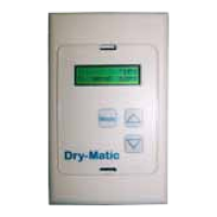
5. Mount Attic and Hall Controllers Run supplied cat 5 patch lead to hall
controller position (as above), attach to hall controller and attic controller.
6. Power Supply Connect a power supply to attic controller isolating switch
(by registered electrician).
Commission the unit
7. Set up the unit using the hall controller, as per commisioning instructions
pp10-13
8. Check Operation check the unit is operating correctly, as for user
operating instructions pp4-5.
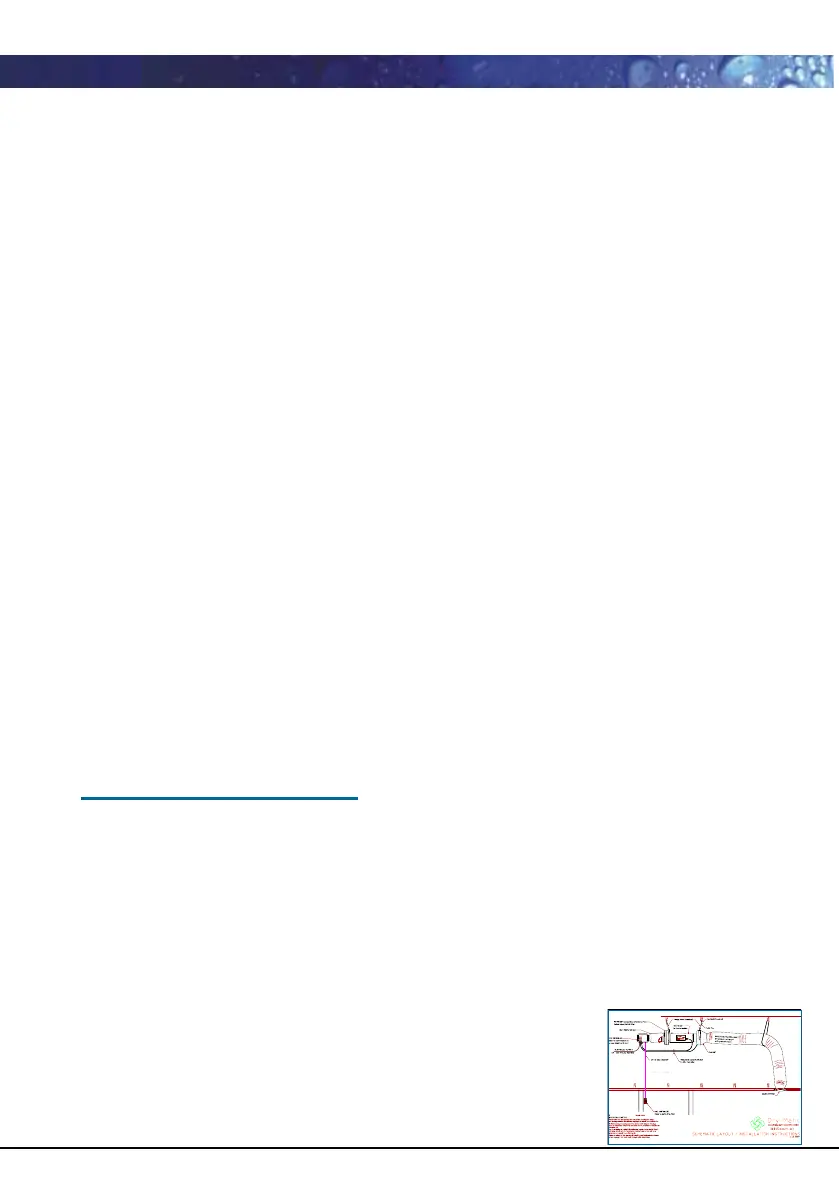
Dry-Matic Installation Instructions (continued)
S
m
o
o
t
h
-
A
i
r
P
r
o
d
u
c
t
s
L
td
See next page
for installation
schematic
 Loading...