SETTING - UP THE DETECTOR
TIM E ADJ USTM E NT: S wi tc h 1 & 2 of DIP -5 U se for S etting “TIM E” - p ro vi de s N.O. re la y. (Four opti on s).
Position Left - “OFF”. Position Right - “ON”.
LED CONTROL: Switch 3 of DIP-5, Use for Setting “LED” - LED Enable / Disable
Position On - LED ENABLE - The RED LED will activate when the detector is in alarm condition.
Position Off - LED DISABLE - The LED is disabled.
NOTE: the state of the switch “LED” does not affect the operation of the relay. When an intrusion is detected, the LED will activate and the alarm
relay will switch into alarm condition for 2 sec.
PIR SENSITIVITY ADJUSTMENT: Switch 4 of DIP-5. Use for Setting “PULSE” - provides sensitivity control of the PIR according to the
environment.
Position Left “OFF” - Low sensitivity For harsh environments. Position Right “ON” - High sensitivity For stable environments.
PET IMMUNITY SETTING: Switch 5 of DIP-5. Use for Settings “PET” 15kg - 25kg
Position Right “ON” - Immunity to an animal up to 15 kg. Position Left “OFF” - Immunity to an animal up to 25 kg
POTENTIOMETER “PIR” - adjustment according to protected area range. Use “PIR” to adjust the detection range between 68% and 100%
(factory set to 84%). R otate the po tenti omet er clockwise to incre ase ran ge, co unter-cl ockwi se to decrease ra nge.
AUDIO VOLUME: Use the potentiometer “VOL.” to adjust the audio volume. Rotate the potentiometer clockwise to increase volume. Rotate
the potentiometer counter-clockwise to decrease volume.
TEST PROCEDURE:
Wait for one minute warm up time after applying 12 Vdc power. Conduct testing with the protected area cleared of all people.
Walk test 1. Remove front cover. Set LED to ON position. 2. Reassemble the front cover. 3. Start walking slowly across the detection zone.
4. Observe that the red LED lights whenever motion is detected. 5. Allow 5 sec. between each test for the detector to stabilize. 6. After the walk
test is completed, you can set the LED to OFF position.
NOTE: Walk tests should be conducted, at least once a year, to confirm proper operation and coverage of
1 2 TIME RELAY CLOSE/OPEN
ON ON 2 SEC
ON OFF 15 SEC
OFF ON 60 SEC
OFF OFF 240 SEC * The N.C. Relay opens for 1.8 - 2 sec. when an alarm occurs.
TECHNICAL SPECIFICATION
Detection Method: Quad (four) element PIR
Power Input: 8.2 to 16 Vdc
Current DrawMono: 115 mA Colour: 150 mA
Temp.
Compensation: YES
Alarm Period: 2 +/- 1 sec
Alarm Output: N.C 28Vdc 0.1 A with 10 Ohm
series protection resistors
Tamper Switch: N.C 28Vdc 0.1A with 10 Ohm
series protection resistor - open
when cover is removed
Warm Up Period: 1 min
LED Indicator: Red LED is ON during alarm
Dimensions: 116mm x 62.5mm x 40mm
(4.56” x2.46” x1.57”)
Weight: 135 gr.
CAMERA TECHNICAL SPECIFICATION
Camera Type: B&W: CCIR or EIA COLOR: PAL or NTSC
Picture Elements:290K (PAL;CCIR) 250K (NTSC;EIA)
Resolution: 420 TV lines(PAL;NTSC), 380 TV lines (CCIR;EIA)
Sensitivity: 0.5Lux - F2.0 (NTSC;PAL), 0.5Lux - F1.2 (EIA;CCIR)
S/N Ratio: Better then 48 dB
Electronic
Shutter Time: 1/60 - 1/100,000 sec (NTSC;EIA)
1/50 - 1/100,000 sec (PAL;CCIR)
Video Output: 1V p-p 75W
LIMITED WARRANTY: Digital Security Controls Ltd, warrants that for a period of 12 months from the date of purchase, the product shall be free of defects in materials and workmanship under normal use and that in fulfillment of any
breach of such warranty. Digital Security Controls Ltd shall, at its option, repair or replace the defective equipment upon returns of the equipment to its repair depot. This warranty applies only to defects in parts and workmanship and not to
damage incurred in shipping or handling, or damage due to causes beyond the control of Digital Security Controls Ltd, such as lightning, excessive voltage mechanical shock, water damage, or damage arising out of abuse, alteration or
improper application of the equipment.
The foregoing warranty shall apply only to the original buyer, and is and shall be in lieu of any and all other warranties, whether expressed or implied and of all other obligations or liabilities on the part of Digital Security Controls Ltd. Digital
Security Controls Ltd neither assumes responsibility for, nor authorizes any other person purporting to act on its behalf to modify or to change this warranty, nor to assume for it any other warranty or liability concerning this product.
In no event shall Digital Security Controls Ltd be liable for any direct, indirect or consequential damages, loss of anticipated profits, loss of time or any other losses incurred by the buyer in connection with the purchase, installation or operation
or failure of this product.
Motion detectors can only detect motion within the designated areas as Shown in their respective installation instructions. They cannot discriminate between intruders and intended occupants. Motion detectors do not provide volumetric area
protection. They have multiple beams of detection and motion can only be detected in unobstructed areas covered by these beams. They cannot detect motion which occurs behind walls, ceilings, floor, closed doors, glass partitions, glass
doors or windows. Any
type of tampering whether intentional or unintentional such as masking , painting, or spraying of any material on the lenses, mirrors, windows or any other part of the detection system will impair its proper operation.
Passive infrared motion detectors operate by sensing changes in temperature. However their effectiveness can be reduced when the ambient temperature rises near or above body temperature or if there are intentional or unintentional sources
of heat in or near the detection area. Some of these heat sources could be heaters, radiators, stoves, barbeques, fireplaces, sunlight, steam vents, lighting and so on.
WARNING: Digital Security Controls Ltd, recommends that the entire system be completely tested on a regular basis. However, despite frequent testing, and due to, but not limited to, criminal tampering or electrical disruption,
it is possible for this product to fail to perform as expected.
Important information: Changes or modifications not expressly approved by Digital Security Controls Ltd could void the user's authority to operate this equipment.
2005 Digital Security Controls Ltd
Toronto, Canada
www.dsc.com
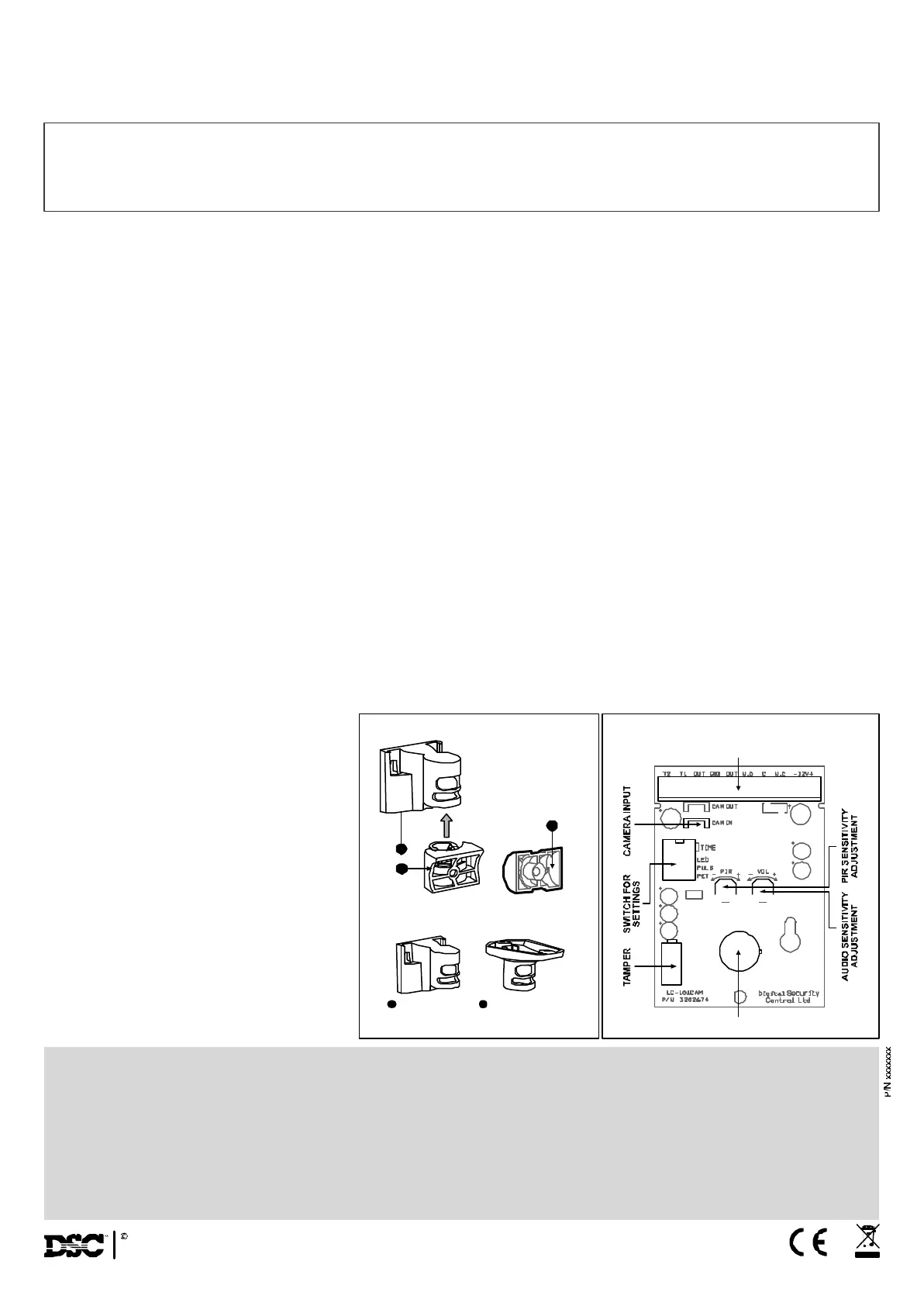
FIG 7 - PCB Layout
FIG 5 - Bracket Installation
Wall Mount
Bracket
Ceiling Mount
Bracket
FIG 6 - Bracket options
1 2
1
3
4
BLOCK CONNECTOR
PYROSENSOR
 Loading...