6
Section 4: Stand-alone Installation (Modes 2&3)
Install the T-Link TL250 in a DSC enclosure (model PC5003C) when used in a stand-alone configura-
tion or with the PC5108 module.
Connect the 12V
DC and GND terminals to the external 12V power source.
NOTE: For UL Listed installations, the power supply used must be UL Listed for the applica-
tion.
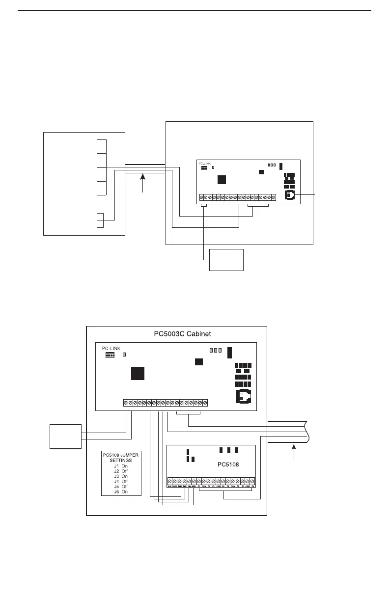
4.1 Stand alone Mode 2 Configuration
4.2 Input Expander (Mode 3 Configuration)
To expand from the 4-zone inputs a PC5108 must be connected to the T-Link. Connect the
Keybus from the PC5108 to the Keybus of the T-Link TL250. Any devices that require 12V
DC,
motion detectors, glass break detectors, etc., will require an external 12V
DC power supply.
PC5003C Cabinet
Note: Wiring between the control panel and the T-Link
TL250 must be enclosed in metal conduit.
Outputs
Input
+12V GND TX RX GND RED BLK YEL GRN IN1 IN2 IN3 IN4 EARTHGND GND1 PGM 2
LK
ACT
SPD
STAT
T-LINK TL250
12V 275mA
UL Listed
Power Supply
CAT5 Cable
(shielded)
10/100 BaseT
Network
PGM1 Trouble Output
IN1 - IN4
Zone Inputs
(Not supervised)
Fire/Burglary
Alarm Panel
Metal Conduit
(20ft max.)
J6
J4
J5
J1
J2 J3
+12V
GND
GND RED BLK
YEL
GRN GNDIN1 GND
EARTH
IN3 IN4IN21 PGM 2
TX RX
LK
ACT
SPD
STAT
Cat5
Network
10/100 BaseT
T-LINK TL250
12V 275mA
UL Listed
Power Supply
PGM1 Trouble Outputs
Metal
Conduit
(20ft max.)
Z1 - Z8 Inputs (NO/NC)
(Not supervised)
IN1 - IN4 Inputs (NO/NC)
(Not supervised)
Connect
to Fire/Burg.
Alarm
Panel

 Loading...