INSTALLATION INSTALLATION
See back page for additional option wiring information.
93043559
93043558
93043560
93044309
93043559
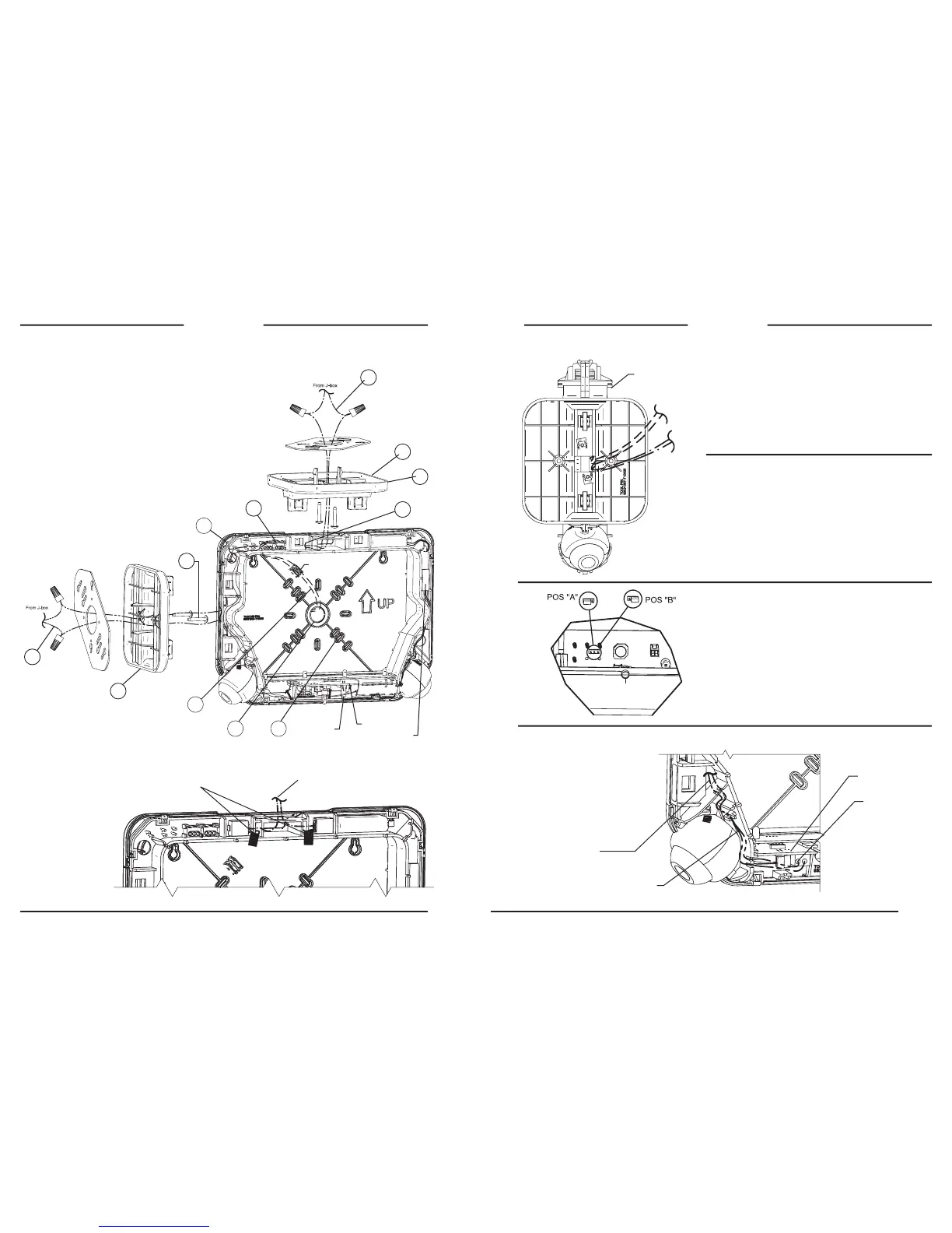
Ceiling, End, or Wall Mount AC Input Leads
Ceiling Mount AC Input Leads
1a. Feed (provided) wires through center of mtg plate and screw mtg
plate to J-box.
2a. Feed wires through center of canopy and snap both canopy
ngers into mounting plate.
3a. Secure Canopy to mounting plate with two (provided) screws.
4a. Route wire leads into sign and make connections using quick
connectors in sign. (Note: Trim wire leads if needed).
End Mount AC Input Leads
1b. Feed AC input wires (provided) through center of mounting plate
and screw mounting plate to J-box.
2b. Feed wires through center square of canopy and snap both
canopy ngers into mounting plate.
3b. Secure canopy to mounting plate with the two screws (provided).
4b. Route wire leads into sign and make connections using quick
connectors in sign. (Note: Trim wire leads if
needed).
Wall Mount AC Input Leads
1c. Remove center K.O. in back plate.
2c. Remove appropriate back plate K.O.’s for J-box
mounting screws.
3c. Feed (provided) wires through center K.O. from
J-box and mount back plate to J-box.
4c. Feed wire under frame dress in wire posts and
make connections using quick connectors in sign
(excess wire to be stuffed back into J-box).
1a
2a
3b
3a
4a
1c 2c
3c
Remote Capacity Wiring Connection
Wire Routing Thru Canopy From J-Box
FAP Option Input Wiring Connection
Route remote capacity leads (provided into
sign, trim to t & make connections using
quick connectors in sign
Route Violet FAP leads
(provided) into sign trim to
t & make connections at
terminal block on option PCB.
Route both FAP wires
in outer wire channel.
NOTE: Afx Violet FAP
wires in any order in
terminal block.
NOTE: If needed apply
FAP label to FAP leads
(provided) for I.D.
Option PCB
FRONT OF SIGN
AC Input
Remote High
Capacity
FAP
Note polarity of wires when
making connections
IMPORTANT: Option connection wires must be run before sign housing
is attached to canopy.
FIRE ALARM PANEL(-FAP) OPTION
FAP option connects to 24 volt AC or DC (Violet wires).
Flash Rate: .5 seconds ON, .5 seconds OFF.
FLASHER MODULE (-FM) OPTION
Emergency Mode Flash Rate: .5 seconds ON, .5 seconds OFF.
AUDIBLE/FLASHER MODULE (-AF) OPTION
Emergency Mode Beep/Flash Rate: .5 seconds ON, .5 seconds OFF.
REMOTE CAPACITY MODEL NOTE
EVC-D4 & EVC-D4I Models Only
Remote capacity models provide sufcient battery capacity to operate 2
additional LED remote lighting xtures or additional run-time. The jumper
setting from the factory will be in position “B”. This will provide the sign
with a longer run-time in emergency mode with no added LED remote
lighting xtures. If the jumper is located to position “A”, you can run 2
additional LED remote lighting xtures.
** Once a remote capacity model is properly installed (jumper is in
position “A”), press and hold the test button for more than 5 seconds
to initiate the load learn process calibrating the 2 additional LED remote
xtures.
The EVC sign is designed to be wall, ceiling or end mounted. Provide standard
and Spectron® equipped signs with single un-switched supply from a 120 or
277VAC branch circuit used for normal lighting in the area to be protected.
For Spectron® remote capacity signs, provide with 120, 240, or 277VAC
branch circuit as needed.
EVC signs are equipped with intelligent wiring. Connect the black wire from
the sign to the HOT building wire (120 or 277VAC) and the white wire to the
building neutral wire.
EXCEPTION: The models with -24K should be connected to 220 - 240VAC
supplies only.
Plug 2-pin battery
connector onto
charger PCB
header.
NOTE: If canopy snaps do not engage sign frame loosen
screws(3b) until canopy is at and all canopy snaps are able to
engage in exit frame.
Charger PCB
Test Button
Battery Pack
Press wires into
wire channel
2b
1b
4b
4c
 Loading...