-
encoste os 2 parafusos inferiores originais (B4) com os relativos
casquilhos originais (B5).
Atenção
luzes traseiras (B6) não fique esmagado entre a pega (H) e o grupo
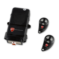
ao binário indicado. Posicione as cablagens debaixo das caixas por-
ta-fusíveis (L) e volte a montar os 3 relés (F) nas respetivas aletas,
como mostrado na figura (X).
Ligue o instrumento de diagnóstico no conector de aquisição dos
dados e habilite o dispositivo antirroubo
no.2 original lower screws (B4) with their original bushings (B5).
During this step, make sure tail light wiring cable (B6) is not pinched
between grab handle (H) and number plate holder unit (B).
Tighten no.4 screws (5) and no.2 original lower screws (B4) to the
specified torque. Place wirings under fuse boxes (L) and refit no.3
relays (F) onto the appropriate tabs, as shown in figure (X).
Connect the diagnostic tool to the data acquisition socket and en-
ISTR 687 / 03
11
 Loading...