EasyManua.ls Logo

Duerkopp Adler 275 User Manual

Duerkopp Adler 275
56 pages
To Next Page IconTo Next Page
Page #1 background imageLoading...
Page #1 background image
275
Spezialnähmaschine
mit Direktantrieb
Betriebsanleitung
Instruction manual
Postfach 17 03 51, D-33703 Bielefeld Potsdamer Straße 190, D-33719 Bielefeld
Telefon +49 (0) 521/ 9 25 - 00 Telefax +49 (0) 521/ 9 25 24 35 www.duerkopp-adler.com
GB
D
Ausgabe / Edition: Änderungsindex Teile-Nr./Part.-No.:
02/2002 Rev. index: 00.0 PrintedinGermany 0791 275740

Table of Contents

Question and Answer IconNeed help?

Do you have a question about the Duerkopp Adler 275 and is the answer not in the manual?

Duerkopp Adler 275 Specifications

General IconGeneral
BrandDuerkopp Adler
Model275
CategorySewing Machine
LanguageEnglish

Summary

Foreword

General Safety Instructions

Scope of Delivery

General and Transport Packing

Assembling the Stand

Assembling the Stand Parts

Assembling stand components.

Completing the Table Top and Fitting it to the Stand

Attaching table top to the assembled stand.

Adjusting the Working Height

Setting the adjustable working height of the table.

Assembling the Machine Head

Fitting the Machine Head

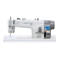
Mounting the sewing machine head onto the table.

Sewing Drive

Items Supplied

List of components for the sewing drive assembly.

Fitting the Control

Mounting the sewing drive control unit.

Fitting the Set-Point Generator

Installing the set-point generator.

Fitting the Knee-Switch

Installing the knee-switch for machine operation.

Fitting the Cable Conduit

Routing and installing the cable conduit.

Fitting the Pedal

Attaching and adjusting the sewing machine pedal.

Electrical Connection

Checking the Mains Voltage

Verifying the correct mains voltage supply for the machine.

Earthing

Properly grounding the sewing machine for safety.

Fitting and Connecting the Sewing-Light Transformer (Optional Equipment)

Installing and connecting an optional sewing light transformer.

Connection Sockets on the DA220C Control

Identifying connection ports on the DA220C control unit.

Connecting the DA220C Control

Connecting various components to the DA220C control.

Checking the Direction of Rotation of the Sewing Drive

Verifying the correct rotation direction of the sewing machine motor.

Checking the Positioning

Checking and verifying the needle's up and down positions.

Machine-Specific Parameters

Adjusting parameters specific to the machine model and subclass.

Operating and Adjusting the DC1500/DA220C Direct-Current Positioning Actuator

DA220C Control Operating and Display Elements

Overview of the DA220C control unit's buttons, LEDs, and display.

Changing Parameter Values at Operator Level with the DA220C Control

Modifying operator-level parameters on the DA220C control.

Calling and Changing Operator-Level Parameters Directly with the DA220C Control

Direct method for changing operator-level parameters on the DA220C control.

Reducing the Maximum Speed with the DA220C Control

Adjusting the maximum sewing speed using the DA220C control.

DA220C Control Operator-Level Parameter List

List of operator-level parameters for the DA220C control.

Changing Technician-Level and Manufacturer-Level Parameter Values

Adjusting technician and manufacturer-level parameters.

Setting Positions with the DA220C Control

Setting the machine's reference and needle positions.

Setting Machine-Specific Parameters with the DA220C Control

Adjusting parameters specific to the machine model and subclass.

Master Reset with the DA220C Control

Resetting all parameters to factory defaults on the DA220C control.

Condition and Error Messages

Explanation of operational states and error codes for the DA220C control.

V810 Operating Panel (Optional Equipment)

Operating and Display Elements on the V810 Operating Panel

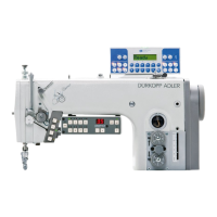
Overview of the V810 operating panel's controls and display.

Key Functions on the V810 Operating Panel

Description of functions assigned to keys on the V810 panel.

Meaning of the Symbols on the V810 Operating Panel

Explanation of symbols used on the V810 operating panel.

Changing Parameter Values at Operator Level

Modifying operator-level parameters using the V810 panel.

Reducing the Maximum Speed

Adjusting maximum speed via the V810 operating panel.

Changing Technician-Level and Manufacturer-Level Parameter Values with the V810 Operating Panel

Adjusting technician/manufacturer parameters using the V810 panel.

Setting Positions with the V810 Operating Panel

Setting machine positions using the V810 panel.

Setting Machine-Specific Parameters with the V810 Operating Panel

Adjusting machine-specific parameters via the V810 panel.

Master Reset with the V810 Operating Panel

Resetting parameters using the V810 panel.

V820 Operating Panel (Optional Equipment)

Operating and Display Elements on the V820 Operating Panel

Overview of the V820 operating panel's controls and display.

Key Functions on the V820 Operating Panel

Description of functions assigned to keys on the V820 panel.

Meaning of the Symbols on the V820 Operating Panel

Explanation of symbols used on the V820 operating panel.

Changing Parameter Values at Operator Level

Modifying operator-level parameters using the V820 panel.

Reducing the Maximum Speed

Adjusting maximum speed via the V820 operating panel.

Quick Information and Quick Settings Entry (HIT)

Using quick information and settings entry features on the V820 panel.

Changing Technician-Level and Manufacturer-Level Parameter Values with the V820 Operating Panel

Adjusting technician/manufacturer parameters using the V820 panel.

Setting Positions with the V820 Operating Panel

Setting machine positions using the V820 panel.

Setting Machine-Specific Parameters with the V820 Operating Panel

Adjusting machine-specific parameters via the V820 panel.

Master Reset with the V820 Operating Panel

Resetting parameters using the V820 panel.

Condition and Error Messages on the V820 Operating Panel

Explanation of operational states and error codes for the V820 control.

Fullness Control in Classes 275-142342 and 275-742642

Checking the Basic Control Setting

Checking and adjusting the basic control setting for fullness.

Setting the LED and Display Brightness

Adjusting the brightness of the control panel's LEDs and display.

Moving to the Reference Position After Each Thread Cut

Setting the machine to move to reference position after thread cut.

Activating the Next Seam Sequence When the Thread is Cut

Configuring activation of next seam sequence after thread cutting.

Rotation in the Reference Position

Checking the rotation behavior in the reference position.

Pneumatic Connection

Connecting the Compressed-Air Maintenance Unit

Steps to connect the compressed-air maintenance unit.

Adjusting the Operating Pressure

Setting and adjusting the operating pressure for pneumatic units.

Lubrication

Sewing Test

Related product manuals