71 … 96
70 … 96
Printed in Germany • Edition 04.18 • Nr. 271 958
Extension module MPA 41xx EM 2/4
Probus DP interface,
Modbus RTU / ASCII
Universal extension module for inte-
grating the MPA 41xx PF in eldbus
systems with up to 31 slaves (without
repeater).
Integrated functions:
- Probus DP interface
- Modbus RTU / ASCII
The bus protocol can be selected by
means of the DIP switch.
Via the bus, commands can be trans-
mitted to the MPA and status informa-
tion can be queried.
BUS protocol presettings
The 4-pin DIP switch is used to select
the bus protocol and to activate the
respective line termination.
The bus protocol must be selected
only with dead voltage. Modications
are impossible during operation.
Bus protocol selection
DIP switch No. 4:
OFF position = Probus
ON position = Modbus
Bus termination
If the termination is activated via
the DIP switch, external termination
resistors must not be plugged into the
output connectors.
If a termination is activated, the termi-
nation of the alternative bus protocol
has to be deactivated in any case.
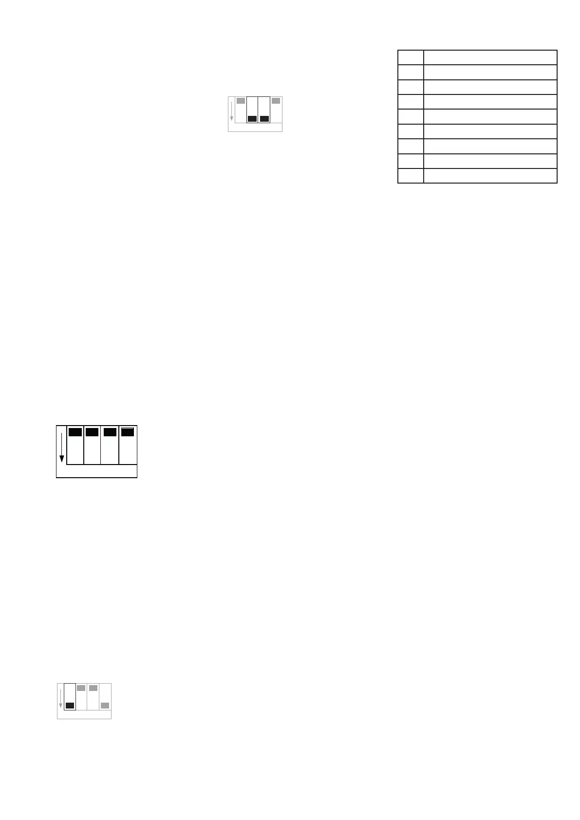
Modbus termination
DIP switch No. 1:
ON position = Modbus termination
resistor 120 Ohm
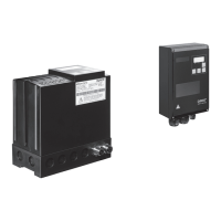
Probus termination
DIP switches No. 2 and 3:
ON position = Probus termination 220
Ohm. Important: Switch both of them
Setting the bus address
The bus address is entered in the P11
parameter (display indication "n").
OFF is displayed if no address has
been entered.
An address between 1 and 99 (up to
126 via VisionBox) can be entered in
the parameter mode. Any modications
will take eect only after a restart.
During operation and error messages,
the current bus address may be seen
by pressing the ← key.
Bus interruption
Modbus
The bus module requires at least one
request per minute. If it is missing, the
behaviour set in P17 is used
Probus
If the cyclic data stream is interrupted,
after a Probus Watchdog period
dened by the master (e.g. 2.5s) the
behaviour set in P17 is used: Tempera-
ture controller operating mode
Probus data
The amount of the input and output
data is dened by the modules in the
enclosed GSD le for Probus.
Probus output data master to MPA
The output data have 8 bits, see table
Command contents of assigned bits:
Bit 0 (heat request) set to 1 by master
= heat request.
Bit 1 If bit 1 (ventilation) is set to 1 by
the master, the air valve is activated in
the states 0 (error), 7 (ame: waiting for
heat request) or state 26 (HT: waiting
for heat request) (P241).
Bit 2 (remote unlocking) set to 1 by
master (at least 0.5 s max. 5 s) = MPA
is unlocked.
Bit 3 If bit 3 is set to 1 by master, the
output X11 is switched on (P19=11).
Bit 4-6 not used
Bit 7 is reserved.
Please set to 0
Eight modules are integrated in the
delivered GSD le. Four, a module for
Basic, Standard, Extended and Spe-
cial Extended, do not receive an output
byte but only input bytes (information
about MPA, see below); however, they
cannot give commands to MPA.
Bit Output byte AB0
0 Heat request
1 Ventilation
2 Remote unlocking
3 Output X11 (P19=11)
4 Not used
5 Not used
6 Not used
7 Reserve (please set to 0)
O
N
1 2 3 4
1 2 3 4
O
N
1 2 3 4
O
N
 Loading...