3. Removing the front panel
Fig.3 Front panel screws
Four screws on bottom and two more on top hold the front panel. The screws are metric size M3
- 3mm diameter (abt.1/8"). Bottom four screws are with cross- recessed Philips-1 heads while
the two top can be with a straight slit (flat screwdriver).
Unscrew the four bottom screws the first and then the two on top while holding the front panel.
Then pull the front panel gently towards front until you release it from the chassis. It will remain
connected wia the mains power switch to the main unit.
After having uninstalled the front panel, you may place it laying near the amplifier, without
disconnecting the power switch. Be very careful not to mixup the switch wires if you would prefer
to disconnect it - the wires are labelled with numbers corresponding to the switch-body contacts
imprint.
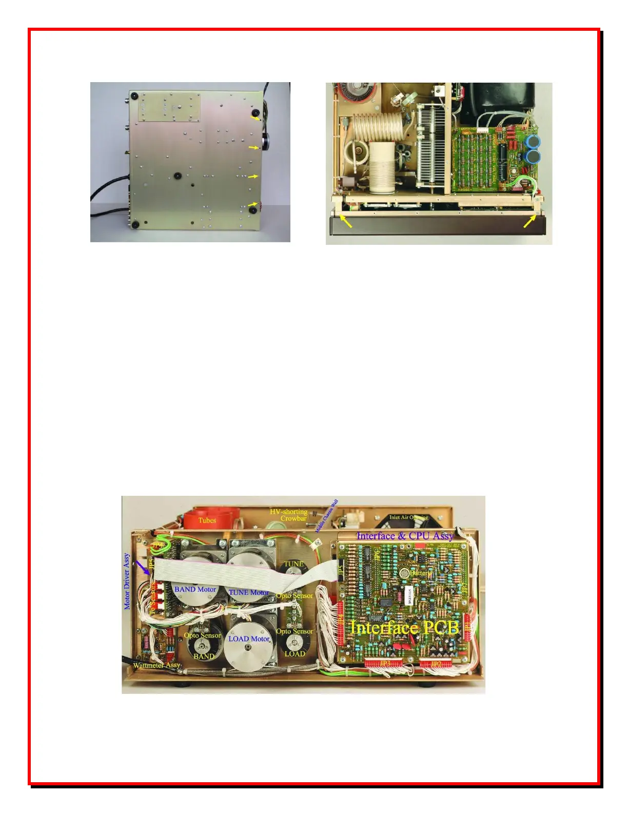
Fig.4 Behind the front panel
 Loading...