Calibration Instructions
The SPD -100 and SPD -100L tachometers are normally factory-
calibrated to the customer-specified number of sensing teeth or
discontinuities, sensing speed, and desired numerical display.
If necessary, refer calculation procedure below to
Calculate Signal Frequency and Gate Time.
To calibrate an SPD -100 or SPD -100L
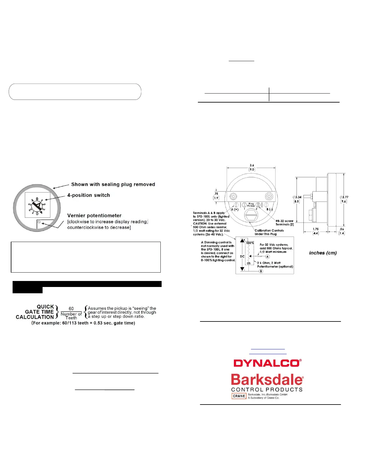
1. Remove the sealing plug on the back of the housing.
2. Apply the calculated signal frequency to terminals 1 and 2.
A Dynalco F-16 or F-15 signal generator is ideal.
3. Select the appropriate gate time range on the 4-position switch.
See label on back of SPD-100 or SPD-100L; or refer Item 3.
4. Adjust the vernier potentiometer for the desired display.
See below.
Example: If 3390 Hz = 1800 RPM, then gate time is 0.53 seconds.
1. Apply 3390 Hz to terminals 1 and 2 on tachometer (no polarity).
2. Turn the gate time range switch to (either) position number 1 to
select gate time range of 0.26–0.72 seconds.
3. Adjust the vernier potentiometer to obtain a display of 1800.
See label on back of SPD-100, SPD-100L for additional
information
1. Calculating Signal Frequency (in Hz)
Multiply RPM times the number of teeth (or discontinuities), then
divide by 60. For example, sensing a ring gear with 113 teeth
rotating at 1800 RPM gives a frequency of 3390 Hz.
Signal Frequency in Hz =
(RPM) x (Teeth or Discontinuities)
60
Signal Frequency in Hz =
((1800 RPM) x (113 Teeth)
= 3390 Hz
60
2. Calculating Gate Time (In seconds)
Divide the number to be displayed on the SPD -100 or SPD-
100L by the corresponding signal frequency.
Gate Time =
1800 RPM
= 0.53 seconds
3390 Hz
3. Gate Time Range Selection on 4-Position Switch
Select either position for each number pair on the switch:
z Position 1: 0.26–0.72 sec. Position 2: 0.72–1.43sec.
Position 3: 1.43–2.85 sec. Position 4: 2.85–5.70sec.
Optional Calibration Method: On-engine
A. Select the appropriate gate time range on the 4-position
switch.
B. Connect the magnetic pickup output to terminals 1 & 2.
C. Adjust vernier potentiometer on SPD-100 or SPD-100L
until its display agrees with another precise digital
tachometer.
OUTLINE AND CONNECTION DRAWING
SPD-100, SPD-100L, F-15, and F-16 are trademarks of Dynalco Controls.
DYNALCO RESERVES THE RIGHT TO CHANGE THESE SPECIFICATIONS WITHOUT
NOTICE
Barksdale Inc.
Barksdale and Dynalco Products
3211 Fruitland Ave
Los Angeles, CA 90058
www.dynalco.com
www.barksdale.com
 Loading...