44
INSTALLATION
5.5.
5.5.
5.
77
77
7
EE
EE
E
LECTRICALLECTRICAL
LECTRICALLECTRICAL
LECTRICAL
C C
C C
C
ONNECTIONONNECTION
ONNECTIONONNECTION
ONNECTION
The SPX Series transmitters have 4-20 mA output. The transmitter power supply and output are supplied
over the same pair of wires.
We recommend that you use twisted, shielded cables as connecting wires.
Observe National Electric Code and national regulations for applications in hazardous areas.
Do not lay connecting cables in the direct vicinity of cables carrying higher voltage or used to switch
inductive or capacitive loads.
5.85.8
5.85.8
5.8
CC
CC
C
ONNECTIONONNECTION
ONNECTIONONNECTION
ONNECTION
A A
A A
A
SSIGNMENTSSSIGNMENTS
SSIGNMENTSSSIGNMENTS
SSIGNMENTS
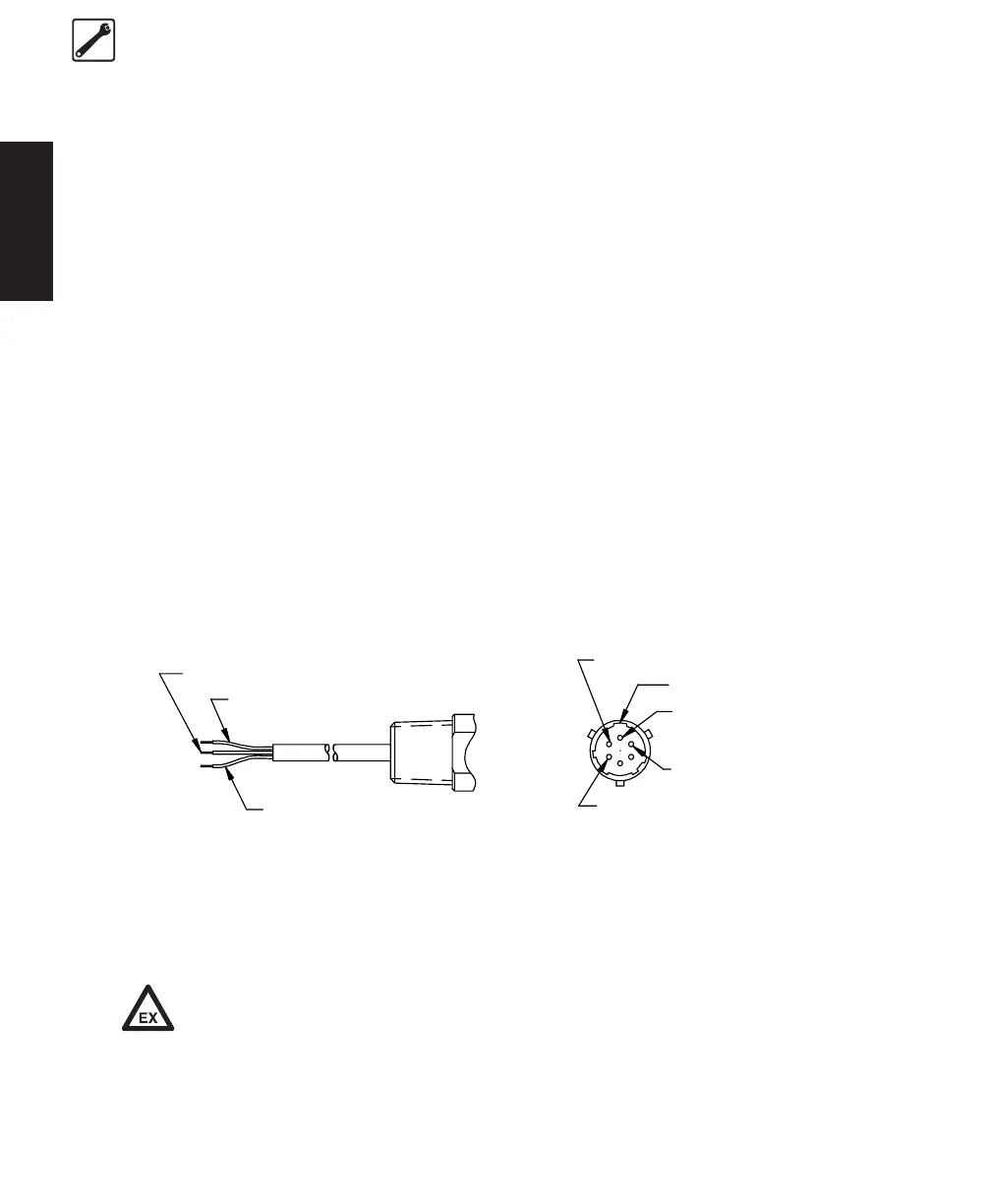
Conduit /LeadsConduit /Leads
Conduit /LeadsConduit /Leads
Conduit /Leads
ConnectorConnector
ConnectorConnector
Connector
Red + Signal/Power A + Signal/Power
Black - Signal/Power B - Signal/Power
Green Case Ground C No Connection
Blue RCal (Option) D No Connection
Orange RCal (Option) E RCal (Option)
F RCal (Option)
Pins C & D are reserved for a special option. In normal operation, they must be left disconnected
(floating).
If the transmitter is installed in hazardous areas, only passive devices such as
switches or resistors may be connected between Rcal functions or any other special
functions. Connection of any active electrostatic circuit or voltage or current source
other than IS supply for the current loop is not allowed.
GREEN= CASE GROUND
BLACK= -SIGNAL/POWER-
RED= SIGNAL/POWER+
CONDUIT/L EADS
E= Rcal (OPTIONAL)
F= Rcal (OPTIONAL)
B= SIGNAL/POWER -
A= SIGNAL/POWER +
CONNECTOR
A
B
C
D
E
F
MASTER KEYWAY
 Loading...