__________________________________________________________________________________________________________________
European Safety Systems Ltd. Impress House, Mansell Road, Acton, London W3 7QH sales@e2s.com Tel: +44 (0)208 743 8880
www.e2s.com Fax: +44 (0)208 740 4200
Document No. D190-00-311-IS-SC Issue: 7 25/11/2020 Sheet 5 of 8
6) Volume Control
The output level of the D1x alarm horn can be set by adjusting
the volume control potentiometer (see Fig 3). For maximum
output, set the potentiometer fully clockwise.
D1xC2AC / D1xC2DC / D1xC1DC / D1xC1AC
Fig. 3 Location of field controls
7) Tone Selection
The D1xC1 & D1xC2 units have 64 different tones that can be
selected independently for the first and second stage alarms.
The tones are selected by operation of the tone setting DIP
switches 1 & 2 (see Fig. 3) on the PCB. The alarm horns can
also be switched to sound the third and fourth stage alarm
tones. The tone table (Table 1) shows the switch positions for
the 64 tones on first and second stages and which tones are
available for the third and fourth stages dependent on the
Stage 1 DIP switch setting.
8) Stage Switching Polarity (DC Units Only)
The D1xC2 and D1xC1 DC alarm horns have the facility to use
either +ve or –ve switching to change the tone to the second,
third and fourth stages. For –ve switching connect the two
headers on the pcb to the left-hand (marked –ve) and centre
pins. For +ve switching connect the headers to the right hand
(marked +ve) and the centre pins. (Refer to Fig. 4)
Fig. 4 Stage Switching Polarity
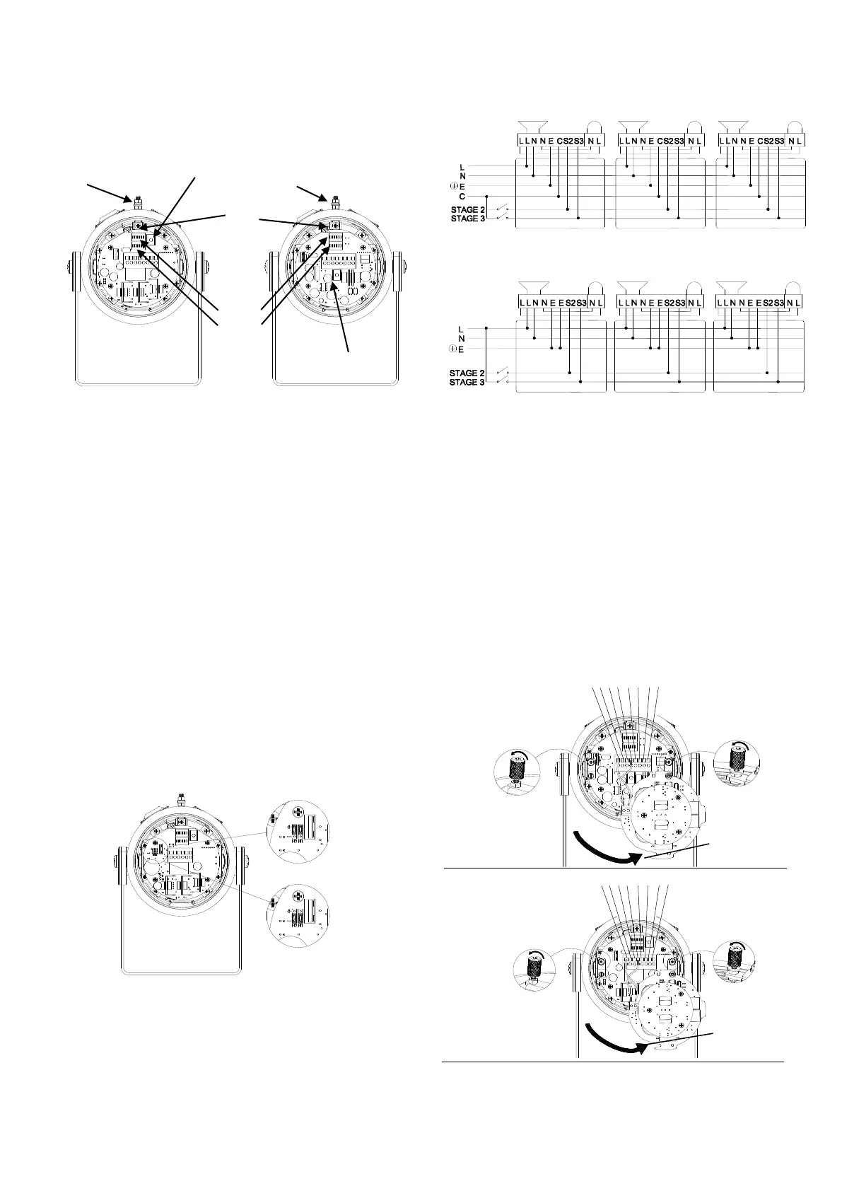
9) AC Wiring
10.1 Wiring Diagrams
Fig 5a. D1xC2 AC Simplified Block Diagram
Fig 5b. D1xC1 AC Simplified Block Diagram
10.2 Units First Stage Tones
Stage one (S1) operation: Simply connect the supply voltage to
the L and N supply terminals, (see fig. 6).
10.3 AC Units Second, Third and Fourth Stage Tone
Selection
To select the second, third and fourth stage tones on the D1x
AC alarm horns.
Stage two (S2) operation : Power L and N, link the common (C)
and S2 terminal.
Stage three (S3) operation : Power L and N, link the common
(C) and S3 terminals.
Stage four (S4) operation : Power L and N, link the common
(C) and both the S2 and S3 terminals.
D1xC1AC Terminals
D1xC2AC Terminals
Fig. 6 AC Terminals
 Loading...