EA4TX – ARS-USB Manual – June. 2024 Page 17
Part 2
Working with the ARS-USB
Once you have wired the ARS-USB board with your rotor and the driver is installed,
you can begin to control the interface.
There are 2 ways you can interact with the product:
COM Port: this port is automatically created each time the PC detect the
ARS-USB
4 Keypad: F1, F2, F3 & F4
2.1 COM Port:
Via the COM port the user or a 3
rd
part program can send and receive commands
to/from the ARS-USB.
The manual: “ARS-USB Commands” describe all commands that are supported.
Some of them are commands for configuring and calibrate the interface. Some others
are used for controlling the appointing. Basically a satellite tracking program or a
logging program will use only those commands for control the appointing.
IMPORTANT NOTE:
The ARS-USB emulates a Yaesu GS232A interface, so any
program that supports this tracker interface with work with it.
2.2 Keypad: F1, F2, F3 & F4
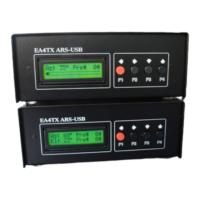
If you have ordered the ARS-USB LCD optional PCB, you have an additional board
with a 16x2 LCD and 4 buttons, which are labeled as:
F1: Which control the Left/CCW movement
F2: Which control the Right/CW movement
F3: Which control the Up movement
F4: Which control the Down movement
So pressing those buttons you can control manually the motors.
If you own an “Azimuth” model, the Up/Down buttons are not required, so in this
case, those buttons are assigned as “PRESET” or “Point and Shoot” control.
So pressing F3/F4 you can change the preset and after an idle period, the ARS-USB
will start the appointing into that preset value.
Remember that you can cancel an appointing at any time, just press F1 or F2.
 Loading...